How to organise code in the large scale

John R Spray
Last update: 2023-10-25
This online book is a work in progress. Feedback is welcome.
Please leave a comment at the end of this book Link to comments section at end of book.
Or e-mail johnspray274<at>gmail<dot>com
Summary
Intuitively, good quality software would allow you to read and understand any one part of the code without also having to read and understand any other part. I call this zero coupling. We are taught the meme loose coupling and high cohesion. Unfortunately, this implies that zero coupling is not achievable. It is said that a zero coupled system would not do anything. But this is only because we confuse design-time coupling with run-time communications. It is entirely possible for parts of a system to have zero knowledge about one another at design-time and still communicate at run-time. We define the word coupling to mean design-time coupling throughout this book. That’s the coupling that matters. By design-time, we mean any time you are reading, writing or understanding code. While understanding code in one module, how much do you have to know about code inside other modules?
We hear the terms compile-time and run-time often, but it is design-time where complexity happens. Modules in conventional code tend to have a lot of coupling in the form of design-time collaboration with one another that causes that complexity. ALA converts that collaborative coupling into cohesion contained in a new module. Here’s how:
At its core, ALA is a set of three architectural constraints:
-
The only unit of code is an abstraction.
-
The only relationship allowed is a dependency on an abstraction that is significantly more abstract.
-
All abstractions must be small - as a guide, less then about 500 LOC.
Many patterns and properties emerge from these three constraints. These are explored throughout this book. But first let’s clarify the three constraints.
The only unit of code is an abstraction

Abstractions are design-time modules. An abstraction is more than a module or encapsulation, which are compiler-time concepts. We call what our brain uses abstractions, and since we are talking about design-time, that’s what we need to call the primary artefact of composition in our software.
An abstraction is a learnable idea or concept. Once learned, it clicks into place like a light coming on, and it becomes an embedded part of your language. That then allows you to compose more specific abstractions using instances of it.
In conventional software development methods, a system is broken into smaller pieces that we call modules, classes, or components. These modules, classes or components tend to have a fixed arrangement with one-another (although an individual piece may be substitutable). This fixed arrangement leads to implicit collaboration with one another to form the system. They are like jigsaw pieces. Specific pieces fit together in a specific way to make a specific picture. The system is not explicit in itself, it is just the result of collaboration of all the individual parts. A jigsaw picture is not explicit, it’s just formed by the collaboration of all the parts.
In contrast to jigsaw pieces, abstractions are like Lego pieces. These pieces are general. Given a set of instances of Lego pieces, you cannot determine a specific arrangement like you can with a jigsaw puzzle. They can be composed in an infinite variety of ways. Any specific arrangement is an explicit artefact in itself, a new abstraction. The parts in this specific arrangement are not collaborating. What makes the system is the particular composition of them. It can be varied without changing the abstractions it is composed of. The specific arrangement is an abstraction in itself, just a more specific one than the Lego pieces it is composed of. That’s going to be how we build software using ALA.
Abstractions have no knowledge of one another, nor the system that uses them.
|
All implicit collaboration between modules in conventional architecture becomes explicit code inside a new abstraction in a higher layer in ALA. |
This first constraint means that the ALA equivalent of a module is an abstraction. The distinction is crucial. Modules that are not good abstractions only provide encapsulation. The term encapsulation means hiding details at compile-time, but not necessarily at design-time. Abstractions are what our brains use, so only abstractions hide details at design-time.
Abstractions are the only mechanism that provides design-time information hiding. When David Parnas coined the term information hiding he meant at design-time. Unfortunately there is a popular meme that information hiding means encapsulation, which only hides at compile-time. The same idea of design-time information hiding has other names such as Alistair Cockburn’s protected variations, and Robert Martin’s version of the OCP (open closed principle).
In the absence of direct computer language support for abstractions, ALA generally implements abstractions as source files (like modules in C). The file usually contains one class, but may contain a small number of classes, interfaces, enums, delegates, typedefs, functions, etc.
Inside an abstraction (source file), there are no relationship rules, or any organisational rules for that matter. It is all considered cohesive code. So internally, abstractions are small balls of mud.
Charles Krueger pointed out that abstraction and reuse are two sides of the same coin. More abstract means more reusable. This makes sense since an abstraction means "commonality drawn from many instances".
More abstract also tends to mean more stable because a more abstract idea is drawn from more instances, and is therefore a more ubiquitous, more fundamental idea. The abstraction 'squareroot' has been stable for thousands of years despite the fact that new instances of its use occur every day.
Software libraries tend to be good abstractions because they were written without knowledge of what will use them. If we conceive of and write abstractions in our applications similarly, without knowledge of the code that will use them, we will also get good abstractions. However, we also need to build useful abstractions. This will require some knowledge of what sorts of applications we are wanting to build. We call that the domain, and the abstractions are called domain specific abstractions.
The only legal relationship is a dependency on a more abstract abstraction
The second constraint is that dependencies must be on abstractions that are significantly more abstract (than the abstraction whose implementation has the dependency).
The word _dependency_ has many meanings in software engineering literature. See
https://www.pathsensitive.com/2022/09/bet-you-cant-solve-these-9-dependency.html for a discussion on the meanings of word dependency. In this book we use the word _dependency_ for design-time (one abstraction depends on another at design-time, which is why we call it a knowledge dependency.) and also compile-time (one class or function, etc, depends on another at compile-time to compile).
When, in ALA, we wire two instances of abstractions, the two abstractions themselves will have no dependency on one another (because abstractions are design-time entities). The classes or functions that implement those abstractions will also have no dependency on one another (because classes/functions are compile-time entities). But the objects or executing functions will still have a dependency on one another at run-time (via an indirection of some kind). This is a run-time dependency between instances or objects or executing functions. When we use the word dependency throughout this book, we are not referring to these types of _run-time_ dependencies. We are refering to all _design-time_ and _compile-time_ dependencies.
In the linked article, _design-time_ dependencies (knowledge dependencies) are referred to as "Program logic / Proof semantics". _Compile-time_ dependencies are referred to as "Static Semantics". And _Run-time_ dependencies are referred to as "Dynamic semantics".
When we use a more abstract abstraction, for example, when a function that calculates standard deviation uses a function that calculates squareroot, the dependency at designtime is only on the concept of squareroot. As a concept, squareroot is stable and learnable. A dependency on a more abstract abstraction is a dependency on a concept that is relatively stable. Because of this stability, there is zero coupling between the code that implements standard deviation and the code that implements squareroot.
For this to work, the abstraction being used must be significantly more abstract than the one whose implementation code uses it.
Communication between instances of peer abstractions

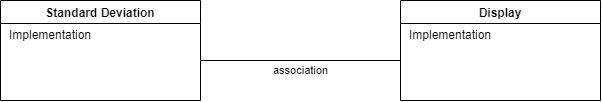
Seemingly, communication is needed between peer abstractions to make a system work. However, in ALA, a dependency from one abstraction on a peer abstraction is illegal. Even a dependency on the interface of a peer abstraction is illegal. For example, if the code implementing standard deviation were to, say, output the result directly to a peer module like a display, it would destroy the standard deviation abstraction. Even if the dependency is on the interface of the display abstraction, the code in standard deviation would still be coupled to a concept that is not more abstract. Standard deviation would no longer be an abstraction. It would no longer be easily learnable as a concept. Any code that used would not be readable in itself. Standard deviation would no longer be reusable without dragging display with it.
Furthermore, over time, the fixed arrangement between the standard deviation function and the display function is likely to lead to the display function providing specifically what the standard deviation function needs, and vice versa. So both functions would tend toward being specific parts of a specific system. They would just be collaborating modules, and not abstractions.
In ALA, abstractions do not communicate. Their instances do. The instances only communicate at run-time but for that to happen something else needs to instantiate them and connect them.
In ALA, there must be a more specific abstraction in a higher layer to represent the system consisting of an instance of a standard deviation abstraction connected to an instance of a display abstraction.
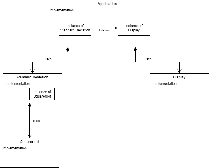
In this example, the higher layer abstraction called Application could just call the standard deviation function and then call the display function. But more commonly in ALA it creates an instance of the standard deviation abstraction and an instance of the display abstraction, and then arranges for these instances to communicate at run-time. The higher layer abstraction can be thought of as representing the user story consisting of an instance of standard deviation connected to an instance of a display.
Classes with ports
In ALA we wont be restricting ourselves to pure functions. We will use classes as well. That’s because in ALA, when we need state, we consider abstraction to be more important than referential transparency (invariant behaviour over time.) Essentially in ALA we are reducing complexity (increasing analysability) by the use of zero-coupled abstractions, whereas in pure functional programming you are trying to reduce complexity only by removing time from the analysis, at least in the functions. Sometimes separating state from functions breaks otherwise good abstractions. An example would be if our standard deviation abstraction receives a stream of data and produces a running standard deviation result. In ALA, such an abstraction has it’s state (SumX, SumXX and N) stored with it, not passed into it. In other words, if state together with some methods makes a good abstraction, then we don’t break it. ALA is therefore highly object oriented. It is object oriented programming as it should have been.
Another example of the need for a class rather than a function might be our display abstraction. A display probably needs some configuration, for example to tell it how many decimal places to display. That should be a separate interface because its going to be used by a different abstraction instance, and at a different time (interface segregation principle). That kind of configuration is usually set once when the abstraction is instantiated, so the configuration state should be stored inside the display abstraction.
ALA is object oriented, but its object oriented in a much more disciplined way than conventional object orientation. That’s because peer classes may NOT have associations. In other words, an object’s communication with another object at run-time may not be implemented by one class having knowledge of another at design-time. Not even on an interface of a peer class.
There must be a more specific abstraction in a higher layer that instantiates the two classes and arranges for them to communicate. This is more than dependency injection. Dependency injection, where one class knows about the interface belonging to another peer class, or a set of substitutable peer classes, is illegal in ALA.
Now we could have the more specific abstraction in the higher layer handle the communication itself by simply calling methods on each of the classes. For the example above, the user story abstraction in the higher layer could call a standard deviation method to get the result, and then call a display method to display it. But that would mean the user story abstraction would be handling the data itself, and furthermore would be implementing the execution model. We don’t particularly like that. We prefer the user story abstraction’s job is just to compose the instances of the two peer abstractions, in a declarative style.
To do this, we build the classes with ports. Syntactically, a port is either a field in a class of the type of an interface, or just implementing an interface, which we already do a lot in conventional code. What makes it a port is the abstraction level of the interface. It has to be fundamentally more abstract to meet ALA’s second constraint. It needs to be a compositional idea. A compositional abstraction is usable by many classes. Ports therefore allow instances of classes to be composed in an infinite variety of ways.
We then simply wire the instances together by their ports. For example, we could make a standard deviation class with an output Dataflow port and a display class with an input Dataflow port. Instances of them can then be wired together by the user story abstraction in a higher layer.
It is important that ports use a significantly more abstract interface that comes from an even lower layer. In ALA, we call these more abstract interfaces programming paradigms. For example, the Dataflow programming paradigm can be used anywhere we need to pipe data into or out of an abstraction. That’s a pretty abstract and reusable idea.
So now, while the standard deviation and display abstractions know absolutely nothing about each other, they both know about the dataflow programming paradigm, and so their instances can be wired to communicate directly at run-time.
Now you may be thinking that the two peer modules are still collaborating on the meaning of data flowing between them. No, that is knowledge held in the Application abstraction above them which wired them together.
Classes can have multiple ports. Ports can use different programming paradigms, not just data flow. For example, the display class could have a second port of type UI. The UI programming paradigm is a different compositional idea. It allows laying out the user interface. A wiring of UI ports means one part of the UI is displayed within another part. For example, an instance of display could be put inside an instance of a panel.
Other types of programming paradigms are invented as we need them in order to meaningfully express requirements. Think of programming paradigms as compositional abstractions. They are abstractions that provide the meaning of composing, such as dataflow, UI layout, events, data schemas or others you can invent.
All dependencies are knowledge dependencies
A dependency on an abstraction in a lower layer means you need to understand the concept the abstraction represents at design-time. It is a knowledge dependency. You could not understand the code that calculates standard deviation without first knowing about the concept of squareroot. However, you do not require knowledge of the concept of a display, so that’s why that dependency is illegal.
Going one layer up, to understand the code in our example user story abstraction requires knowledge of both the concept of standard deviation and the concept of display. It is therefore fine for the user story abstraction to have dependencies on both and compose an instance of standard deviation and an instance of display.
Abstractions that are more abstract become part of your language. We take this for granted when we use library abstractions, such as squareroot. In ALA, all lower layers make up the language for the next higher, more specific, layer until we are able to express the application’s user story abstractions.
Good and bad dependencies
This is an alternative way of viewing ALA’s dependency constraints.
Conventional code contains both good and bad dependencies. Good dependencies are when we use abstractions, such as when we use a library class.
There will typically be very high numbers of bad dependencies in conventional applications. These bad dependencies are usually put there for different modules of a program to inter-communicate. They are also used to break a large module up into smaller modules - hierarchical decomposition. These smaller pieces may start with a stated functionality, but they are pieces specific to the module they are used by and therefore actually more specific than the module.
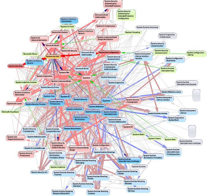
Bad dependencies make the dependency diagram look like the one on the right. It is an actual dependency graph of a conventional application that was completely cleaned up by ALA. My partner says it looks like two ferris wheels engaged in a mating act. Even if we manage to avoid cyclic dependences, there are still typically many bad dependencies.
In ALA, all bad dependencies are illegal. Normally in conventional code we don’t distinguish between good and bad dependencies. We consider them all to be necessary if the system is to work. But it turns out that systems can be built using only good dependencies.
Good dependencies are not just good - they are really good. We want as many of them as possible, because then we are reusing our abstractions. Bad dependencies are not just bad - they are really bad. They cause a growing tangled network of complexity.
Since bad dependencies are illegal in ALA, how do parts of the system communicate? Well, each bad dependency simply becomes a line of code completely inside a higher layer abstraction. That line of code connects two instances of abstractions. There it is cohesive with other lines of code that connect other instances of abstractions that together make a whole user story.
If you think about it, circular dependencies come about because there is circular communications. Circular communications is perfectly valid. When you stop representing communications with dependencies, and start representing them with wiring code, circular wiring makes perfect sense. When you use only good dependencies, circular dependencies, and the whole dependency management problem just goes away.
Nearly all relationships in a typical UML class diagram are bad dependencies. In ALA, the only legal UML class relationship is composition (filled diamond arrow), and then only if the class being used is more abstract (in a lower layer). Now, when you use an abstraction, you always refer to it by name, not use an arrow on a diagram. You wouldn’t draw a line on a diagram when using a library function such as squareroot - you would just use squareroot by name as if it’s part of your language. Similarly, you wouldn’t draw 'instantiates and uses' relationships in an ALA application on a UML diagram. So, it turns out that if you drew a UML class diagram of an ALA application, you would just get disconnected boxes sitting in space. There would be no lines at all, They would be arranged in layers, as described below. The UML class diagram is completely redundant in ALA. In fact the UML class diagram, by encouraging bad dependencies between would-be peer abstractions, has probably caused more damage to software than any other software engineering meme. UML class diagrams are evil.
Metrics
Unfortunately, common metrics in use today do not understand abstractions. For example, CBO (Coupling of objects), (which, despite its name, is the total number of classes with dependencies to or from a given class) does not distinguish between good and bad dependencies. It just counts them all, making the metric completely useless.
ALA recognises the importance of using abstractions and composability in dealing with complex systems. If metrics don’t also take into account this importance, they cannot work well.
A common problem when calculating CBO is whether or not to include library classes. Intuitively we know that library classes are abstractions. We see them as part of our programming language. So we feel they should not be included in the metric. The same should apply to all good dependencies - those that are dependencies on the knowledge of a concept in a lower layer. If CBO counted only bad dependencies, it would be an extremely useful metric. Perfect software would require the metric to be zero.
If the CBO metric should first identify all potential abstractions, and then identify their abstraction levels relative to each other. Since abstraction and reuse are two sides of the same coin, Robert Martin points that we can use the number of uses (dependencies) on a given class as an estimate of its abstraction level. In this way it may be possible to take some bad legacy code and and suggest which classes should become abstractions at which levels. If the programmer agrees with the tool, then he can proceed to refactor out all the bad dependencies using ALA. This will require intrducing new specific abstractions at a higher layer in which put wiring code for each bad dependency. That in turn will require the invention of composition abstractions (interfaces) in a lower layer to allow the creation of ports on the classes that had the bad dependencies.
Emerging layers
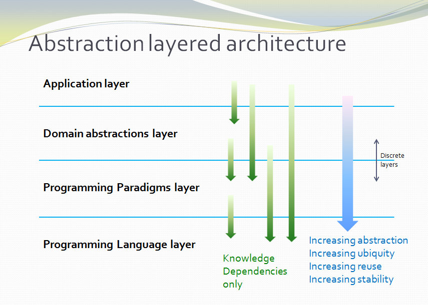
Because of the constraint that an abstraction that is depended on must be significantly more abstract, abstractions form layers. This gives the architecture its name: abstraction layered architecture. We give the layers names that reflect the types of abstractions that tend to go in them - application layer, domain abstractions layer, programming paradigms layer.
Each layer becomes a folder and a namespace in the implementation. This makes it very easy to know how to arrange our source files. The folders for each layer are not nested.
For large applications, another layer called the features layer or user stories layer comes into the picture between the application and domain abstraction layers. A specific application abstraction in the top layer then just composes a set of features or user stories needed in that specific application, and sets up any communication that may be needed between them.
There is no 'hierarchical' or 'nested' structure in ALA. In other words, abstractions cannot be contained within abstractions. There is no analog of a sub-module or sub-component, no such thing as a sub-abstraction. Abstraction layers replace hierarchical containment. This is because lower layer abstractions must be visible for reuse, not hidden inside an encapsulation hierarchy.
Once you have learned the concepts of the abstractions available in lower layers, it is easy to read and understand code in higher layers. Reading a line of code that uses an abstraction by name is like reading any other line of code. A good abstraction is when you don’t need to follow the indirection and go and read the code that implements the abstraction. For example, when we see a use of squareroot, if our brain has already learned the concept of squareroot once, we can concentrate on the code that is using the squareroot. We do not have to change context and go and read the code that implements squareroot. ALA is about achieving that level of readability for every single dependency in the entire application.
All abstractions must be small

This third constraint prevents us from conforming to the first two constraints by simply putting everything into one big ball of mud abstraction. That’s obviously not desirable, so we need this constraint to force us to create abstractions from which we can compose instances to make our application.
Abstractions are internally highly cohesive, which means that all code inside them is inter-related. Internally they are a small ball of mud. If that highly interrelated code is to be understood, it needs to be small.
A rule of thumb is around 100 to 500 lines of code. If the code is in diagram form (which will often be the case for reasons we will explain later), we should limit the size to 100-500 nodes plus edges.
If an abstraction contains more than 500 lines, it is starting to get over the brain limit for other programmers to understand. If abstractions average less than 100 lines of code, we will likely have more abstractions than we need to, and burden ourselves with an unnecessarily high number of them to learn. The sweet spot, which relates to the size of our brains, is somewhere in-between.
Other emergent patterns

ALA emerges many other patterns and properties. Many of them are already known about in software engineering, which is not surprising - such things as DSLs (Domain Specific Languages), Dependency Injection, Composite and Decorator patterns, monad like composition, etc.
There are often subtle but important differences. For example, wiring instances of abstractions in ALA uses dependency injection, but you can’t use interfaces that are specific to the classes being wired.
Another example is the observer pattern (publish/subscribe). It can be used to achieve calls going up the layers at run-time in ALA, but may not be used between peer abstractions in the same layer. If they are in the same layer, the subscriber’s reference to the publisher would be an illegal dependency. A line of code in an abstraction in a higher layer must do the subscribing, which is effectively what the wiring pattern described below is.
Inheritance is not used in ALA. We only use composition because inheritance breaks abstractions.
Wiring pattern
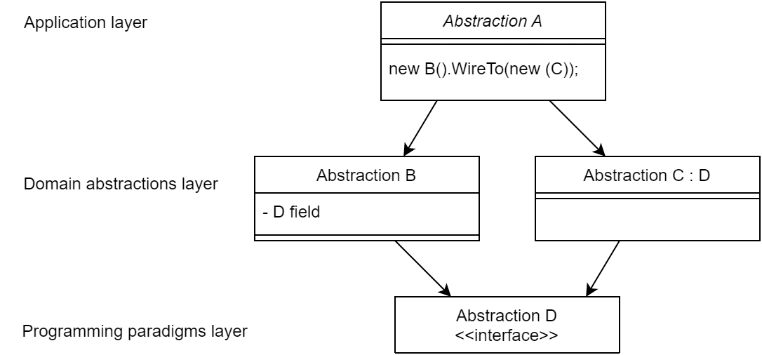
I use the wiring pattern shown on the right frequently to build ALA applications.
Abstraction A in the application layer has legal dependencies on abstractions B and C in the domain abstractions layer. B and C have dependencies on D in the programming paradigms layer.
D is a programming paradigm interface. This interface is not owned by B or C. It is its own abstraction representing a compositional idea, such as Dataflow or UI layout.
B and C have ports of type D. B’s port is implemented as a field of type D, and C’s port is implemented by implementing D’s interface.
A can create an instance of B and an instance of C and wire them together because they have compatible ports. Wiring causes the instance of C, cast as the interface, to be assigned to the field in B.
While abstraction B and abstraction C know nothing about each other, the instances of B and C can communicate with each other at run-time because they both know about the programming paradigm interface, D.
A tiny example
Every chapter has an example, and we do the same here in the summary. Unlike most pedagogical sized examples, these examples progressively become non-trivial. Yet because of ALA’s power, they remain uncomplicated and easy to understand.)
Requirement: Make a switch control a light.
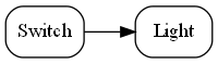
The diagram above is not documentation. Nor is it a high-level architectural view of the solution. It is the solution. It is the implementation for the user story abstraction. It contains all the detail needed for an executable user story. The diagram is literally compiled. Let’s do that now by hand:
Application layer
Here is the diagram converted to text form:
var system = new Switch().WireTo(new Light());
system.Run();
Given this code, it is not difficult for any programmer to write the necessary Switch and Light domain abstractions as classes, together with a Dataflow programming paradigm abstraction as an interface to make that code execute. We will do that in a moment.
In conventional code, we would likely have broken the system up into two modules, one for the switch and one for the light. The switch might directly call a method in the interface for the light, or vice versa. In ALA you can’t do that. The concepts of Switch and Light, already handed to us as abstractions in the words of the requirements, must remain as abstractions. At design-time, they can’t know about one another and they can’t know about the specific system. As abstractions they can’t communicate with one another. But at run-time, instances of them, after having been wired together, can communicate with one another.
The abstract concept of dataflow is invented to allow instances of Switch and Light and many other things to communicate with data at run-time. Dataflow is an even more abstract abstraction. It resides in the programming paradigms layer. It is a stream of data without end. It is not a specific interface of either Switch or Light. It allows Switches and Lights to be wired arbitrarily to anything using the same dataflow concept.
The Switch-Light system is also an abstraction, albeit a more specific one than Switch or Light. Multiple instances of it could be used in a building. Its purpose is to know about the system comprising a light and a switch connected together. It knows about Switch, Light and Dataflow as abstract concepts but doesn’t know anything about their implementation details.
The system diagram is a direct, formal restatement of the requirements. So the diagram is three things in one: The formal statement of requirements, the high level architecture, and the executable. One source of truth for all three. Conventional software engineering usually has three different documents for these, which then must be kept synced.
When the program is this small, it looks like we just created four abstractions when two modules would have done. However, by creating an application layer abstraction to represent the system level knowledge, and a programming paradigm layer abstraction to represent the concept of Dataflow, we make several powerful improvements to the code that are important as the application scales up in size:
-
There is now an explicit place that cohesively implements the requirement instead of having the requirement’s implementation distributed in an obviscated way inside Switch and Light. What is loose coupling between modules in conventional code becomes cohesive code completely contained inside a higher (more specific) abstraction in ALA. Changes to the requirements are made in this one place.
-
The code inside all the abstractions: System, Switch, Light and Dataflow are zero-coupled with one another. Every abstraction’s internal code is readable in isolation.
-
Being abstractions, Switch and Light are reusable. They are reusable in the same application or in other applications in the domain. Dataflow is even more reusable.
-
Programming paradigms provide the meaning of connecting together two instances of domain abstractions. We can use multiple different programming paradigms in the one top level design. ALA is said to be polyglot in programming paradigms. This makes it very expressive.
-
Switch and light do not need a shared understanding for the interpretation of data (a shared language). We think that shared languages are necessary because people need a shared language to communicate. So we tend to create modules that work in the same way. These are sometimes referred to as contracts. If Switch and Light were modules, they would need to agree on something like true means on and false means off. In ALA, this type of coupling is also gone. The knowledge about interpretation of data is wholly contained inside the user story abstraction in the higher layer. This may seem trivial in this simple case, but it becomes enormously significant in larger programs and distributed programs.
-
If the instances of Switch and Light are deployed to different physical locations, the Switch-Light system is still a single cohesive abstraction describing that system. Normally, conventional programs are decomposed first into modules across physical locations, but in ALA you always compose first by user stories, regardless of the physical deployment of its constituent domain abstraction instances. This will also be highly significant as the system scales up in size.
-
Switch and Light are easily testable with unit tests.
-
Testing the system abstraction is exactly acceptance testing. In ALA, you always test with dependencies in place, but you mock the ports. Just as you would not mock out a dependency such as squareroot, you do not mock any dependencies in ALA, because all dependencies are knowledge dependencies. Testing the system abstraction means testing that an instance of the switch and Light system works.
-
The writing of the Switch and Light abstractions can be handed off to different individuals or teams because, as abstractions, they know nothing about each other, and they know nothing about the System. In fact abstractions will be better quality if the teams do not collaborate with each other so that the abstractions themselves do not collaborate. (Corollary of Conway’s law.)
-
In terms of methodology, instead of decomposing the Switch-Light system into parts, we compose it from abstractions. This point may seem subtle, but it is profoundly important. The conventional divide and conquer methodology of splitting a system into smaller but collaborating parts until the parts are small enough to implement is arguably the prevalent approach in traditional software engineering. It causes a lot of damage. It result in parts that are more specific than the system (can’t be reused for anything) and, more significantly, inter-collaborating parts that have implicit knowledge of each other. The meme divide and conquer should be replaced with invent and compose.
Here is skeleton code of the two domain abstractions.
Domain abstractions layer
// domain abstraction
class Switch
{
    // port
    private IDataFlow<bool> output;

    // called from internal code (not shown) when it detects a hardware change
    private void SwitchChange(bool newState)
    {
        output.Send(newState);
    }
}// domain abstraction
class Light : IDataFlow<bool> // port
{
IDataFlow<bool>.Send(bool data)
{
if (data) // turn on the light
else // turn off the light
}
}Each of these abstractions implements a port, which allows instances of them to be wired using the programming paradigm, DataFlow.
You may be wondering why the Switch’s output port is private. That’s because we wan’t the public interface of Switch to just be the 'configuration interface' used by the system abstraction when it instantiates a Switch. The WireTo method is designed to be able to wire the private port.
Here is our programming paradigms layer which contains the DataFlow abstraction:
Programming Paradigms layer
// Programming paradigm: DataFlow
interface IDataFlow<T>
{
    void Send(T data);
}
In ALA, we frequently use the wiring pattern, as depicted by the diagram in Figure 4, which consists of instantiating domain abstractions and wiring them together by ports that use an even more abstract interface. The wiring pattern is quite ubiquitous, and therefore comes from a foundation layer that resides below the Programming Paradigms layer:
Foundation layer
public static object WireTo(this object a, object b)
{
    // using reflection:
    // 1. Find a private field in object "a" that matches in type an interface implemented by object "b".
    // 2. Cast and assign object "b" to that field in object a.
    // 3. Return object "a".
}
Note: A basic implementation of WireTo is listed in Chapter Two. You can get the source for a WireTo extension method from one of the Github repositories for the example projects in several following chapters.
Note: ALA does not require the use of reflection. I like to use reflection because it allows me to use an extension method to get a WireTo operator implemented for all domain abstractions. It allows me to make specifying the port name optional. It also allows me to make the port fields in the class private so they do not look like part of the public configuration interface to the layer above. And it spares me from writing setter methods for every port.
Instead of using a WireTo function, and if you are generating wiring code from the diagram automatically using a tool, and you make the port fields public, you could generate wiring code like the following:
new Switch().output = (IDataFlow<bool>) new Light();Now that we know how to express requirements by composition of domain abstractions, let’s quickly demonstrate the ease of maintenance of our application:
Requirement: Add a sensor to turn on the light when the switch is on and it is dark. And give a feedback indication:
(For these small examples, we will manually generate code from the diagrams.)
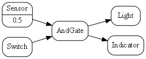
Here is the diagram converted to text form:
var andGate = new AndGate();
new Main
    .WireTo(new Switch()
        .WireTo(andGate
            .WireTo(new Light())
            .WireTo(new Indicator())))
    .WireTo(new Sensor(threshold:0.5)
        .WireTo(andGate))
    .Run();
We just invented some new domain abstractions: AndGate and Sensor, again directly implied by the requirements.
One of the domain abstraction instances has a configuration of 0.5. This is a threshold for expressing the requirement clause "is dark".
Notice that this application is easier to write in this way than it would be in conventional C code. This is because the programming paradigm we are using, dataflow, suits the expression of these requirements. Most C code to do even such a simple requirement as this would likely already be messy in the way it handles run-time execution.
The astute reader will notice that the AndGate can’t implement IDataFlow<bool> twice for its two inputs. In later projects, we will show how we work around this completely unnecessary constraint of most languages.
You may also notice that the fanout from the output of the AndGate to both the Light and the Indicator won’t work because an output port can be wired only once. We show how this implementation problem is solved in later projects as well.
Now that we have some reusable domain abstractions and programming paradigms, let’s quickly write another trivial application:
Requirement: Turn on the light from a tick item in the Tools menu of a PC application, and give an indication in the status bar when the light is on.
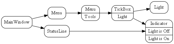
Here is the diagram converted to text form:
var indicator = new Indicator( {"Light is off", "Light is On"} );
new MainWindow()
    .WireTo(new Menu())
        .WireTo(new Menu("Tools")
            .WireTo(new TickBox(label:"Light")
                .WireTo(new Light())
                .WireTo(indicator)
            )
        )
    )
    .WireTo(new StatusBar()
        .WireTo(indicator) // put the indicator on the UI
    )
    .Run();
Here we are introducing some graphical UI, so we invented another programming paradigm for "UI layout". It is used between all the UI elements: MainWindow, Menu, Tickbox, StatusBar, Indicator. Wiring things together using that programming paradigm means things are arranged inside things on the UI.
Notice how ALA is polyglot in programming paradigms. We use two programming paradigms, UI layout and dataflow, to express the user story. Notice also that we don’t separate UI from business logic and data models as we do in conventional architectural layering patterns. These are highly cohesive things from the perspective of user stories and ought to be kept together. Instead, we separate the implementations of the domain abstractions. It is still easy to swap out, for example, the UI implementation. The diagram above could be implemented as a web application or a desktop application by swapping between two sets of UI domain abstraction implementations.
Let’s do an application to browse for and display a (dynamic content) CSV file on a grid, filtered by a user specified name, and sorted by names. The CSV file has headings that will display in the grid.
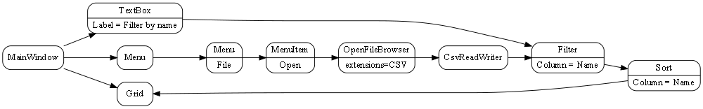
The wiring between the MeniItem and the OpenFileBrowser uses an Event-driven programming paradigm.
The wiring between the CSVReadWriter, Filter, Sort and Grid uses a programming paradigm that allows dynamic row and columns of data to flow. The Grid abstraction is able to pull rows of data as needed.
Here is the diagram converted to text form:
var grid = new Grid();
var csvReaderWriter = new CsvReaderWriter
var filter = new Filter() {Column = "Name"};
new MainWindow()
    .WireTo(new Menu()
        .WireIn(new Menu("File"))
        .WireIn(new MenuItem("Open"))
        .WireIn(new OpenFileBrowser(extensions = {"csv"} ))
        .WireIn(csvReaderWriter)
        .WireIn(filter)
        .WireIn(new Sort() { Column="Name" })
        .WireIn(grid) { Column="Name" }
    )
    .WireTo(new TextBox(Label="Filter by name")
        .WireTo(filter)
    )
    .WireTo(grid)
    .Run();
Note: if you already have monads in your programming library for things like sorting and filtering (such as LINQ or reactive extensions), then instead of creating new domain abstractons for Filter and Sort, you could just create a domain abstraction called _query_ and use LINQ or reactive extensions code to configure the query instance.
Note: WireTo() returns its first operand (this). WireIn() is the same as WireTo() except that it returns its second operand. These operators support the fluent coding style being used in this hand compiled code so that we don't have to think of names for every instance of an abstraction.
The methodology we have been following is that you write the application code (diagram) first (or part of it), just focusing on expressing the requirements. This causes you to invent domain abstractions and programming paradigms. Then you come up with an execution model that will make the programming paradigms execute. For example, the two interfaces listed below might be what you would come up with for the Event and PullTable programming paradigms:
// Programming paradigm: Event driven
interface IEvent
{
    void Execute();
}// Programming paradigm: TableDataFlow
interface IPullTable : IEnumerable<List<string><T>>
{
List<string> GetHeaderLabels();
}This interface handles dynamic data (types unknown at compile-time) by crudely using strings. In a later project we will show a more sophisticated IPullTable interface that uses static typing for fields known at compile-time and an ExpandoObject for dynamic fields. We will also do a push version.
Both Filter and Sort will have both input and output ports of type IPullTable. The List in the IEnumerable represents one row of the table.
Don’t worry, we won’t be creating new programming paradigm abstractions at this rate for long. In fact we already have most of the ones we will use in all our example projects in this book.
Notice how in the above examples, we have used software engineering patterns we already know about, just in a different way. There is DSL (Domain Specific Language), Dependency Injection (which is what the WireTo operator does), Event driven programming, XAML-like UI layout (without the XML), RX (Reactive programming), monad-like wiring up, and the fluent style.
Notice how the application diagram in each case is both a direct representation of the requirements and the executable. It is executable because unlike conventional higher level or architecture diagrams, ALA application diagrams do not leave out details from the requirements. They are a complete expression of them. Instead, they leave out all details of implementation, which are taken care of by domain abstractions and programming paradigm abstractions.
To the extent that requirements are cohesive, so the code that expresses them should be. For example, we do not try to separate the specific UI, I/O, business logic, persistent data etc into different modules because they are highly cohesive for a given requirement. Most other architectural patterns, such as MVC, do separate in this way, which creates coupling. Instead we reduce the problem in a different way - through the use of domain abstractions which provide reusable aspects of implementation. All knowledge and details from the requirements end up in the application layer, but that’s all that goes there.
Note: A graph-like structure is showing up in these small applications because each requirement in itself contains a graph of connections. ALA embraces this and makes it explicit, which is why the requirements are best expressed as diagrams. In conventional code, the graph structure is still there, but it is typically obfuscated as many intermodule relationships, making it hard to see. Worse still, the natural cycles in the graph of relationships in the requirements, would cause circular dependencies among conventional modules. Conventionally, some of these dependencies are broken by using pulling data half the time rather than pushing, or worse still, using indirections such as the observer pattern. These removals of dependencies don’t make the relationships themselves go away, they just make them harder to see. In ALA the inter-module relationships go away and become connection code purely contaned inside a single module.
Although the fluent style is a nice way to hand-compile these small diagrams, code like this with indenting and nested brackets does not scale up well for large diagrams. (It is still better than the tangled web of dependencies they would form in conventional modular code though.) But we can do better. We will not be hand-writing code like this for large applications - we will automatically generate the code from the diagrams.
Finally, the wiring pattern used in the examples above is only one possible way of meeting the fundamental ALA constraints. For example, ALA can also be applied to functional programming using monads as domain abstractions. But we will use explicit objects with explicit classes and the wiring pattern shown above in most of our examples. The wiring itself is implemented by a field in the objects, but that field is immutable. ALA may appear to be synonymous with this wiring pattern, but actually ALA is just the three fundamental constraints stated at the beginning of this introduction.
This online book is a work in progress. ALA is a research in progress. Please don’t hesitate to provide feedback to the e-mail address given at the top or in the comments facility at the end.
I would like to acknowledge the help of Roopak Sinha at AUT (Auckland University of Technology) for his significant academic contributions and ideas for ALA, and the contributions of many students who have implemented ALA projects, and helped refine the ALA methodology.
1. Chapter one - What problem does it solve?
If you have already experienced difficult to maintain code, big balls of mud, spaghetti code, or the CRAP cycle (Create, Repair, Abandon, rePeat), you can probably skip this chapter.
However, the example at the end is pretty cool - it starts with the type of typical C code that I see most students write, and then refactors, it step by step, into ALA compliant code - you should take a look at that.
The problem that ALA solves can be seen as any one of the following perspectives.
1.1. The Big Ball of Mud

Brian Foote and Joseph Yoder popularized this term in their 1997 paper. It describes the default architecture when no other architecture is used. A similar term is spaghetti code. I think it describes the architecture of most software even when so-called architectural styles, such as layering, are used.
ALA is an in-the-large strategy to organise code. It provides the constraints needed for the code structure to not degenerate into a big ball of mud. As the software life cycle continues, retaining the organisation becomes easier rather than harder.
1.2. Simplify down the overwhelming set of architectural styles, patterns, and principles
There are many traditional architectural styles, patterns, principles and paradigms. The problem of structuring software code to meet quality attributes involves mastering an overwhelming number of them. Here are some examples:
-
loose coupling and high cohesion, information hiding, separation of concerns
-
DSLs, aspects, model driven, MVC, inversion of control, functional programming, UML Class diagrams, sequence diagrams, activity diagram, state diagram.
-
Views, Styles, Patterns, Tactics, Models, ADL’s, ADD, SAAM, ATAM, 4+1, Decomposition
-
CBD/CBSE, Components & Connectors, Pipes & Filters, n-tier, Client/Server, Plug-in, Microservices, Monolithic, Contracts, Message Bus
-
Modules, Components, Layers, Classes, Objects, Abstraction, Granularity
-
Semantic coupling, Syntax coupling, Temporal coupling, existence coupling, Good and bad dependencies, Collaboration
-
Interfaces, Polymorphism, Encapsulation, Contracts, Interface Intent
-
Execution models, Event-Driven, Multithreaded, Mainloop, Data-driven, Concurrency, Reactor pattern, Race condition, Deadlock, Priority Inversion, Reactive
-
Principles: SRP, OCP, LSP, ISP, DIP; MVC, MVP, etc
-
Design Patterns: GOF patterns, GRASP patterns, Layers, Whole-Part, Observer, Strategy, Factory method, Wrapper, Composite, Decorator, Dependency Injection, Callbacks, Chain of Responsibility, etc
-
Expressiveness, Fluency, DDD, Coding guidelines, Comments
-
Programming Paradigms, Imperative, Declarative, Object oriented design, Activity-flow, Work-flow, Dataflow, Function blocks, Synchronous, State machine, GUI layout, Navigation-flow, Data Schema, Functional, Immutable objects, FRP, RX, Monads, AOP, Polyglot-Programming Paradigms
-
Messaging: Push, Pull, Synchronous, Asynchronous, Shared memory, Signals & Slots
-
Memory management, Heap, Persistence, Databases, ORMs
-
Waterfall, Agile, Use cases, User stories, TDD, BDD, MDSD
Mastering all these topics takes a lifetime. Even if you can, juggling them all and being able to use the right ones at the right time is extremely taxing on any developer. Add to that the mastering of technologies and tools, keeping to agile sprint deadlines, and commitment to your team and management, it is an almost impossible task. 'Working code' tends to be what the team is judged on, especially by project managers or product owners who have no direct interest in architecture or even the Definition of Done. They don’t want to know about the rather negative sounding term, "technical debt".
Most texts will tell you that these are all tools and that you need to use the right tools for each job. It all depends, they say, on the particular system, and its particular functional and non-functional requirements. In most cases they end up being used in an ad-hoc manner that doesn’t work well. In some cases their use is actually harmful.
Being a pre-worked recipe of the aforementioned styles and patterns, ALA probably contains no truly novel ideas. Every aspect of what ALA does can be found already done by someone. However the combination that ALA uses is as far as I know unique.
Some ingredients from the above list are accentuated in importance more than you might expect (such as abstraction). Some are relatively neutral. The biggest surprise for me during the conception process of ALA was that some well-established software engineering memes seemed to be in conflict. Eventually I concluded that they were in-fact bad (such as UML class diagrams). We will discuss these in detail in subsequent chapters.
Like any good recipe, the ingredients work together to form a whole that is greater than the sum of the parts. The resulting code quality is significantly ahead of what the individual memes do by themselves. It continues to surprise me just how effective, and enjoyable, the simplified view is.
1.3. An optimal solution for quality attributes
ALA is an optimal solution for these quality atributes:
-
Readability
-
Complexity
-
Maintainability
-
Testability
-
Understandability
-
Modifiability
-
Extensibility
-
Dependability
-
Reusability
It is independent of any specific domain, so it is a general reference architecture. By optimal, I mean that it makes these qualities as good as they can be.
If other non-functional requirements are also important, ALA provides a good starting point.
-
Performance
-
Availability
-
Scalability
-
Portability
-
Distributability
-
Security
-
Usability
-
Fault-tolerance
Even if the ALA structure must be compromised in places for other qualities, it is still better to start with these quality attributes optimised and deviate from them as necessary. As it happens, the maintainability resulting from ALA frequently makes other quality attributes easier to achieve as well. For example, in an ALA application it is often easy to make performance optimizations in the execution model that don’t affect the application code. For example, an application first written to run on a single processor can more easily be distributed to multiple processors. Or, you can port an application by swapping out domain abstractions without changing the application code.
1.3.1. Readability

Modules don’t necessarily make pieces of code that are readable in isolation.
ALA code is readable, not because of style, convention, comments or documentation, but because any one piece of code appears to you as a separate uncoupled little program that is readable in complete isolation.
1.3.2. Complexity
There is a meme in the software industry that says that the complexity of software must be some function of its size. This need not be so. With proper use of abstraction it is possible to have complexity that is constant regardless of program size. ALA makes use of this.
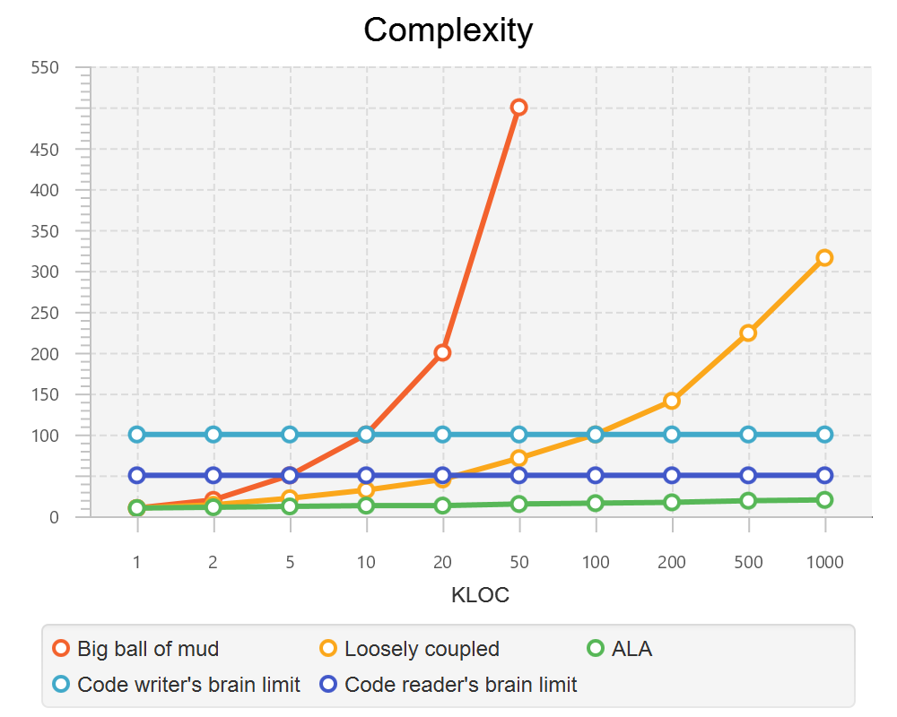
This is a qualitative graph comparing the complexity of an ALA application with that of a big ball of mud and an average loosely coupled application. This is further explained in chapter seven here.
1.3.3. Maintainability
The maintainability effort over time should qualitatively follow the green curve in the graph below because as software artefacts are written, their reuse should reduce the effort required for other user stories. Product owners seem to have an innate sense that we manage to organise our code such that this happens. That is why they get so frustrated when things seem to take longer and longer over time, and they often ask us "haven’t we done this before". In practice, too often we follow the red curve. Maintenance eventually gets so difficult that we want to throw it away and start again. We reason we can do better. My experience is that we don’t do better when we rewrite. We just create another mess. It is just a psychological bias on the part of the developer caused by a combination of a) the Dunning Kruger effect and b) the fact that it is easier to read our own recently written code than someone else’s.
If we apply all the well known styles and principles, the best we seem to be typically manage is the orange curve, which comes from the COCOMO models, and which still has maintenance effort continuously increasing.
When we did an experimental re-write of a legacy application using ALA, and measured its maintainability attribute, it comes out as improving over time by several different measures.
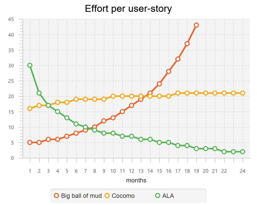
ALA is based on the theoretical architectural constraints needed to follow the green curve.
1.3.4. Testability
In ALA all code is testable. ALA makes it clear when to mock and when to test with dependencies in place. All dependencies are left in place, because all dependencies are design-time or knowledge dependencies.
Therefore, when testing the application layer abstractions, they are tested with their domain abstraction dependencies. In other words, testing the application is acceptance testing.
Testing domain abstractions is easy with units tests because abstractions are zero-coupled. Mocks objects are wired to ports.
1.4. Structure hidden inside the modules
The problem in most large code bases is that the system structure, the structure at the largest scale, is not explicit. It is distributed inside the modules themselves. Collaboration between modules is implicitly hidden inside them. Finding this structure, even for a single user story can be time consuming. I have often spent a whole day doing that, doing countless all-files searches following function calls or method calls of the user story through many modules just to end up changing one line of code in the end. Many developers I have spoken to can identify with this experience.
I call this situation SMITA (Structure Missing in the Action). The internal structure is sometimes drawn as a model - high-level documentation of the hidden structure. But such models are a secondary source of truth.
It can get a lot worse as the system gets larger. In a seemingly bizarre twist, the more loosely coupled you make the elements, the harder it gets to trace a user story because of the indirections. Some people conclude that loose coupling and being able to trace through a user-story are naturally in conflict. They are actually not in conflict.
ALA is an architecture that has full indirection at runtime while at the same time having no indirection at design-time because the system is implemented all in one cohesive plave.
1.5. The CRAP cycle
Typical bright young engineers come out of university knowing C++ or Java (or other C*, low-level, imperative, language that mimics the silicon), and are confident that, because the language is Turing-complete, if they string together enough statements, they can accomplish anything. At first they can. There hardly seems a need for a software architect to be involved. And besides, we are told that a design can emerge through incremental refactoring.
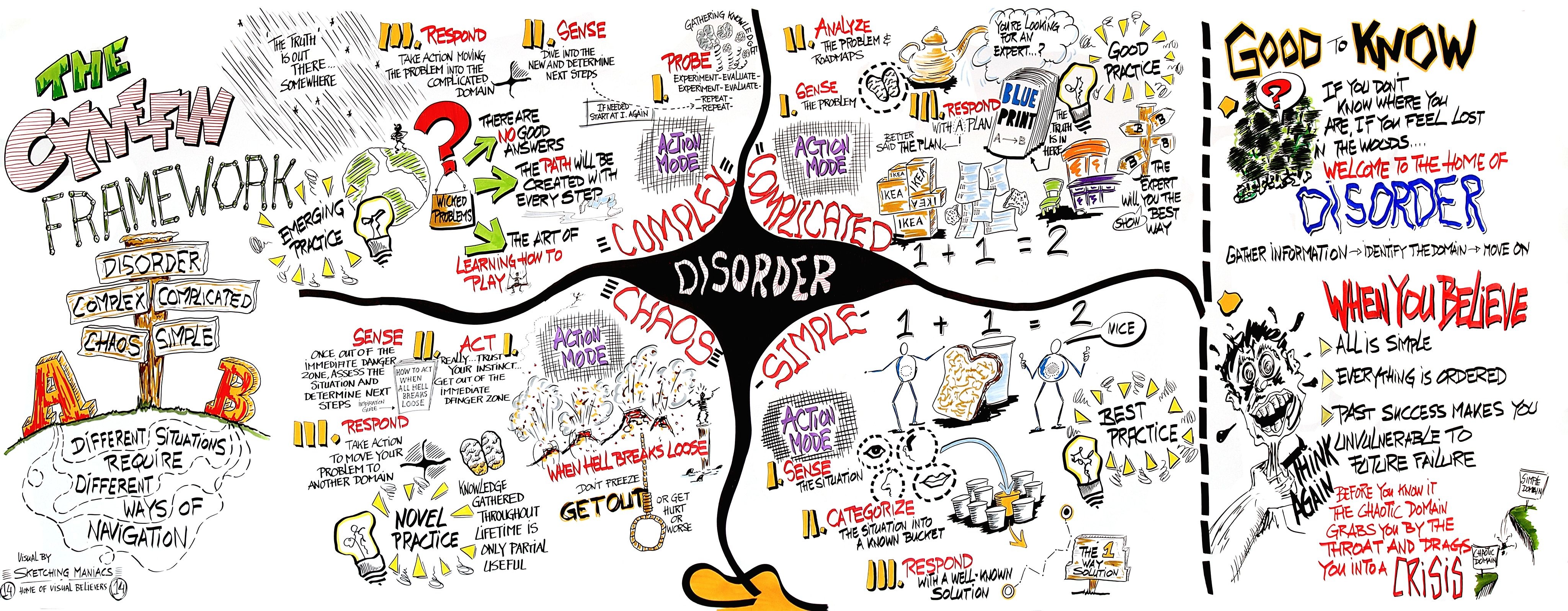
As the program gets larger, things get a little more complicated, but the young developer’s brain is still up to the task, not realizing he has already surpassed anyone else’s ability to read his code. He is still able to get more features working. One day parts of the code 'transition' to complex. It becomes somewhere you don’t want to go. On the Cynfin diagram, it has moved from the complicated quadrant to the complex quadrant. And now it is trapped there. It is too complex for refactoring.
The incremental effort to maintain starts to eat away and eventually exceed the incremental increase in value. This now negative return causes the codebase itself to eventually lose value, until it is no longer an asset to the business.
It has transitioned to chaos. It will be abandoned. When a new bright young engineer who knows C* arrives, he looks at the legacy codebase and is convinced that he can do better. And the cycle repeats. This is the CRAP cycle (Create, Repair, Abandon, rePlace). ALA is the only method I know that can prevent the CRAP cycle.
1.5.1. A short history of ALA
From early on in my career, I experienced the CRAP cycle, not so much rewriting applications, but trying to avoid the mess when writing new ones. When starting from a blank piece of paper, I would research all the architectural styles and principles. I would come across things like 'loose coupling', and I remember asking myself, yes but how does one accomplish that? Each time I would still fail.
I started searching for a pre-worked, generally applicable, 'template architecture' that would tell me what the organisation of the code should look like for any program. I searched for such a thing many times over a long career and never found one. Some would say that this is because the highest level structure depends on project specific requirements.
Finally, near the end of my career, I have that template meta-structure that’s applicable to all programs. The turning point was when I noticed two (accidental) successes in parts of two projects. These successes were only noticed years later, 15 years in one case and 5 years in the other. They had each undergone considerable maintenance during that time. But their simplicity had never degraded and their maintenance had always been straightforward. It was like being at a rubbish dump and noticing two pieces of metal that had never rusted. "That’s weird", you think to yourself. "What is going on here?"
One of them had the same functionality as another piece of software that I had written years earlier. That software was the worst I had ever written. It was truly a big ball of mud, and maintenance had become completely impossible, causing the whole product to be abandoned. So it wasn’t what the software did that made the difference between good and bad. It was how it was done.
Analysing the common properties of those two code bases, gave clues that eventually resulted in a theoretical understanding of how to deal with complex systems. This meta-structure is what I now call Abstraction Layered Architecture.
Subsequently, I ran some experiments to see if the maintainability and non-complexity could be predictably reproduced. These experiments, which have worked spectacularly well so far, are discussed as a project at the end of each chapter.
1.6. Example project - Thermometer
In this example project, we will first do conventional C code using functions, then refactor it into abstraction layers, and finally improve on that using classes.
Functions have an execution model we are already familiar with, making this first example easier to understand. However, keep in mind that, for whole programs, this execution model does not usually make a good programming paradigm. An emergent property of ALA is its support of multiple and diverse programming paradigms including your own. We do this to improve expressiveness of the requirements.
Nevertheless, functional composition is a passable programming paradigm for a tiny, dedicated embedded program in a micro-controller such as our thermometer. Let’s have a look at some typical code:
1.6.1. Bad code
#define BATCHSIZE 100 #include "configurations.h"
void main()
{
int temperatures[BATCHSIZE];
ConfigureTemperaturesAdc();
while (1)
{
GetTemperaturesFromAdc(temperatures); // gets a batch of readings at a time
ProcessTemperatures(tempertures)
}
} void ProcessTemperatures(int adcs[])
{
float temperature;
for (i = 0; i<BATCHSIZE; i++) {
temperature = (adcs[i] + 4) * 8.3; // convert adc to celcius
temperature = SmoothTemperature(temperature);
ResampleTemperature(temperature);
}
} void ResampleTemperature(float temperature)
{
static int counter = 0;
counter++;
if (counter==15)
{
DisplayTemperature(temperature);
counter = 0;
}
} // smooth the reading before displaying
float SmoothTemperature(float temperature)
{
static filtered = 0;
filtered = filtered*9/10 + temperature/10;
return filtered;
} #include "configurations.h"
void ConfigureTemperaturesAdc()
{
// configure ADC channel 2 to do DMA BATCHSIZE values at a time
}
float GetTemperaturesFromAdc(int temperatures[])
{
for (i = 0; i<BATCHSIZE; i++) {
temperature[i] = ReadAdcChannel(2); // pseudocode here for the adc read
}
}At first this code wont look that bad, but that’s only because the whole program is so small. It looks modular, but you still have to read all of it to understand any part of it. That’s possible for small programs, but of course that strategy won’t scale up.
As we are taught to do, different responsibilities of the thermometer implementation have been separated out into smaller pieces with smaller responsibilities, although ProcessTemperatures appears to have three responsibilities. The problem is that all the pieces are in some way collaborating to make a thermometer. They are all coupled in some way, both explicitly or implicitly. That’s why we have to read all the code to understand the thermometer. Scale this up to 5000 lines of code, and we will have a big mess.
We are going to refactor the program using the ALA strategy:
-
every piece of knowledge about 'being a thermometer' will be in one function
-
that 'Thermometer' function will be at the top
-
that function will do no real work itself
-
how to do more abstract things will be put into other functions
-
those functions will not know anything about temperature or thermometer
-
The top layer function will compose the abstract functions it needs to build a thermometer
1.6.2. Toward ALA code
 #define BATCHSIZE 100
 void main()
 {
    int adcs[DMABATCHSIZE];
    float temperatureCelcius;
    float smoothedTemperatureCelcius;
    while (1)
    {
        GetAdcReadings(adcs, 2, DMABATCHSIZE);  // channel=2
        for (i = 0; i<BATCHSIZE; i++) {
            temperatureInCelcius = OffsetAndScale(adc, offset=4, slope=8.3);
            smoothedTemperatureCelcius = Filter(temperatureCelcius, 10);
            if (SampleEvery(15))
            {
                Display(FloatToString(smoothedTemperatureCelcius, "#.#"));
            );
        }
    }
} // offset and scale a value
void OffsetAndScale(float data, float offset, float scale)
{
return (data + offset) * scale;
} // IIR 1st order filter, higher filterstrength is lower cutoff frequency
float Filter(float input, int strength)
{
static float filtered = 0.0;
filtered = (filtered * (strength-1) + input) / strength
return filtered;
} // Returns true every n times it is called
bool SampleEvery(int n)
{
static counter = 0;
counter++;
if (counter>=n)
{
counter = 0;
rv = true;
}
else
{
rv = false;
}
return rv;
}The code now begins to be arranged into two abstraction layers, the application layer and the domain abstractions layer. The application is now the only function that knows about being a thermometer. (It is still doing some logic work - the 'for loop' and 'if statement', which we will address soon.)
All the other functions are now more abstract - they know nothing about thermometers - GetAdcReadings, OffsetAndScale, SampleEvery, Filter, FloatToString, and Display. Notice that the word 'thermometer' has been removed from their names, and none of them contain constants or any other references that are to do with a thermometer or temperature.
These abstract functions give you six things:
-
Abstract functions are way easier to learn and remember what they do
-
Abstract functions give design-time encapsulation i.e. zero coupling.
-
Abstract functions can be understood by themselves
-
Abstract function interfaces are way more stable - as stable as the concept of the abstraction itself
-
Abstract functions are reusable
-
Abstract functions are testable
-
As a consequence of 1., the application function can also now be understood by itself
Now let’s go one more step and create an abstraction to do what that for loop does: This may seem like a retrograde step, but we need to understand this mechanism to move to our final goal of expressing the requirements through pure composition of abstractions. We want to move the 'for loop' out into its own abstraction, but we don’t want to move the code that’s inside it. We accomplish this by putting the code inside it into another function and passing that function to the for loop function:
1.6.3. Further toward ALA code
 #define DMABATCHSIZE 100
 void main()
 {
    int adcs[DMABATCHSIZE];
    float temperatureCelcius;
    float smoothedTemperatureCelcius;
    ConfigureAdc(2, DMABATCHSIZE)
    while (1)
    {
        GetAdcReadings(adcs, 2, DMABATCHSIZE);  // channel=2
        foreach(adcs, func1);
    }
 }
 void func1(float adc)
 {
    temperatureInCelcius = OffsetAndScale(adc, offset=4, slope=8.3);
    smoothedTemperatureCelcius = Filter(temperatureCelcius, 10);
    if (SampleEvery(15))
    {
        Display(FloatToString(smoothedTemperatureCelcius, "#.#"));
    );
} void foreach(int values[], void (*f)(int))
{
for (i = 0; i<sizeof(values)/sizeof(*values); i++) {
(*f)(values[i]);
}
}"func1" is not an abstraction - you cannot give it a name and learn a simple concept of what it does. That’s why I gave it a non-descript name. The content of func1 is cohesively just part of the thermometer application. The name func1 only serves as a symbolic connection within cohesive code - nothing more than a wiring between two points in the program. In this case func1 is immediately below where it is used in the same small file. But as a program grows, these symbolic wirings are always hard to follow. You would need to resort to text searches to find these connections. These types of connections can be numerous and unstructured in larger programs, and the best way to deal with them is diagrams. A line on a diagram is like a symbolic connection between two points, but it’s anonymous and easy to follow. However, this particular one can be dealt with in text form. So let’s go ahead and remove it by using an anonymous function directly as the second parameter of foreach:
 #define DMABATCHSIZE 100
 void main()
 {
    int adcs[DMABATCHSIZE];
    float temperatureCelcius;
    float smoothedTemperatureCelcius;
    ConfigureAdc(2, DMABATCHSIZE)
    while (1)
    {
        GetAdcReadings(adcs, 2, DMABATCHSIZE);  // channel=2
        foreach(adcs, (adc)=>{
            temperatureInCelcius = OffsetAndScale(adc, offset=4, slope=8.3);
            smoothedTemperatureCelcius = Filter(temperatureCelcius, 10);
            if (SampleEvery(15))
            {
                Display(FloatToString(smoothedTemperatureCelcius, "#.#"));
            );
        });
    }
 }
It uses the lambda syntax '()⇒{}', which if you are not already familiar with, is worth getting used to. It’s a function without a name, so think of the ⇒ as being instead of the name of the function, the round brackets as the parameters, and the curly braces as the body of the function.
The next thing we want to do is get rid of the while loop, get rid of the indenting, and stop handling the data that is being passed from one function to another. None of them have anything to do with a thermometer. All those intermediate holding variables: adcs, temperatureCelcius, etc are all just symbolic connections. They are too much work when we just want to compose our thermometer from abstractions.
The while loop and all the indenting are there only because we have 'execution flow' tied in with our composition of abstractions. Basically we want to make control of execution flow another abstraction so that the thermometer can be built by just composing abstractions rather than writing executing code.
To do this we will first show how its done using monads. If you don’t know about monads just skip this section as we don’t need this step to understand our final goal. But for those who do understand monads, it is interesting to visit this step to see why the functional programming guys invented them. Then in the following step we will go to ordinary classes with ports instead of monads.
1.6.4. Brief detour: composing with monads
 void main()
 {
    program = new ADC(channel=2, batchSize=100)
    .foreach()
    .OffsetAndScale(offset=4, slope=8.3)
    .Filter(strength=10)
    .SampleEvery(15)
    .NumberToString(format="#.#")
    .Display();

    program.Run();
 }
Monads have allowed us to separate execution flow from composition flow. The composition flow is now a pure dataflow paradigm. Data will flow from the ADC to the display, so that is directly represented by the composition. How it executes is separated out, and we will go into how that works shortly. Let’s first understand the 'composition' and why this is so important.
Even if you don’t understand how the monads work, you can see that syntactically the program is now very nice because all it does is compose instances of abstractions, and configure them with constants to be a thermometer. The composition is not declarative - it is dataflow, because dataflow suits how to describe the thermometer. If we let go of how it executes and just trust that the dataflow from one instance of an abstraction to the next works, the program becomes highly readable.
We are using the word 'composition' here to mean the things we are joining together in adjacent lines of code. It can also mean joining boxes with lines in a diagram. Think of a composition as analogous to the adjacent notes in a music score, which are always played successively. If the lines of code are statements or function calls, we are composing things for imperative execution by the CPU. If the lines of code are data processors, we are composing things for successive processing of data. The output of one passes directly to the input of the next.
If we are stuck with thinking in terms of imperative execution flow (the only way of thinking in the C language) we will need to try hard to let that go, and realize that in ALA, 'composition' can be any programming paradigm you want.
Also notice that the first statement just builds the program. Then the second statement sets it running. This two stage aspect of monads is common in the programming paradigms we will use in ALA. It is because the underlying execution flow is not the same as the flow of the programming paradigm. We first wire it up, and then we tell the wired up structure to 'execute'.
There is a second important difference from the while loop version. The while loop version handled the data itself. Each function returned the data which was stored in a local, otherwise useless, variable and then passed into the next function. The monad code doesn’t do that. Instead, it creates and wires together objects which will, at run-time, send the data directly from one to another via an interface. This does not mean that the abstractions themselves know anything about each other - they are still zero coupled. But the application now doesn’t have to deal with data. It just has to compose abstractions.
Lastly, here’s how monads actually execute - the execution model. Don’t worry if this doesn’t make sense.
Each function in the program statement (the function after each dot) executes once at the start. They are not executed when the program is running. Each of these functions first instantiates an object (using new), and secondly wires that object to the previous object.
The functions wire the objects together using an abstract interface. Common interfaces used for monads are IEnumerable or IObservable. These interfaces support iteration of data, by returning an IEnmerator or IObserver. If using the IEnumerator interface, there is a simple method in the interface that pulls data from the previous object. If using the IObseravble interface, there is a simple method in the interface that pushes data to the next object. So IEnumerable/IEnumerator and IObservable/IObserver as abstractions are pretty much just the concept of dataflow, the same abstract concept we will use in the ALA version.
1.6.5. Composing with plain objects
Here is the same program as above, but we are using plain classes with ports instead of monads. We use the 'new' keyword explicitly to create the instances of abstractions, and explicitly wire them together using a wiring function. It’s a little less succinct than the monad version, but the idea of "objects with ports that you wire together like electronic components" is easier to understand, and more versatile. It is necessary for developers to be able to write new domain abstractions, so this needs to be easy.
 void main()
 {
    program = new ADC(channel=2,batchSize=100)
        .WireIn(new Foreach())
        .wireIn(new OffsetAndScale(offset=4, slope=8.3))
        .wireIn(new Filter(strength=10))
        .wireIn(new SampleEvery(15))
        .WireIn(new NumberToString(format="#.#")
        .wireIn(new Display());

    program.Run();
 }
The wireIn method is doing dependency injection.
The WireIn method returns the new object, so it is possible to string WireIns together. This is called fluent syntax.
1.6.6. Using multiple programming paradigms:
Monads are generally not versatile enough to handle multiple ports of different programming paradigms, which we will want in ALA programs. Monads usually only support dataflow. But what if we want to also compose the UI, or event-driven? What if we want to compose transitions between states of a state machine? In ALA, we are able to do all this in the one application, in the same way - using whatever programming paradigms are the best way to express the requirements.
Some instances of abstractions will need to take part in multiple paradigms, such as both UI and dataflow. When we boil down the description of our requirements to pure composition, our composition will often be a graph of relationships. And when you have a graph, your composition is best described by a diagram.
To illustrate this let’s add some UI to our thermometer:
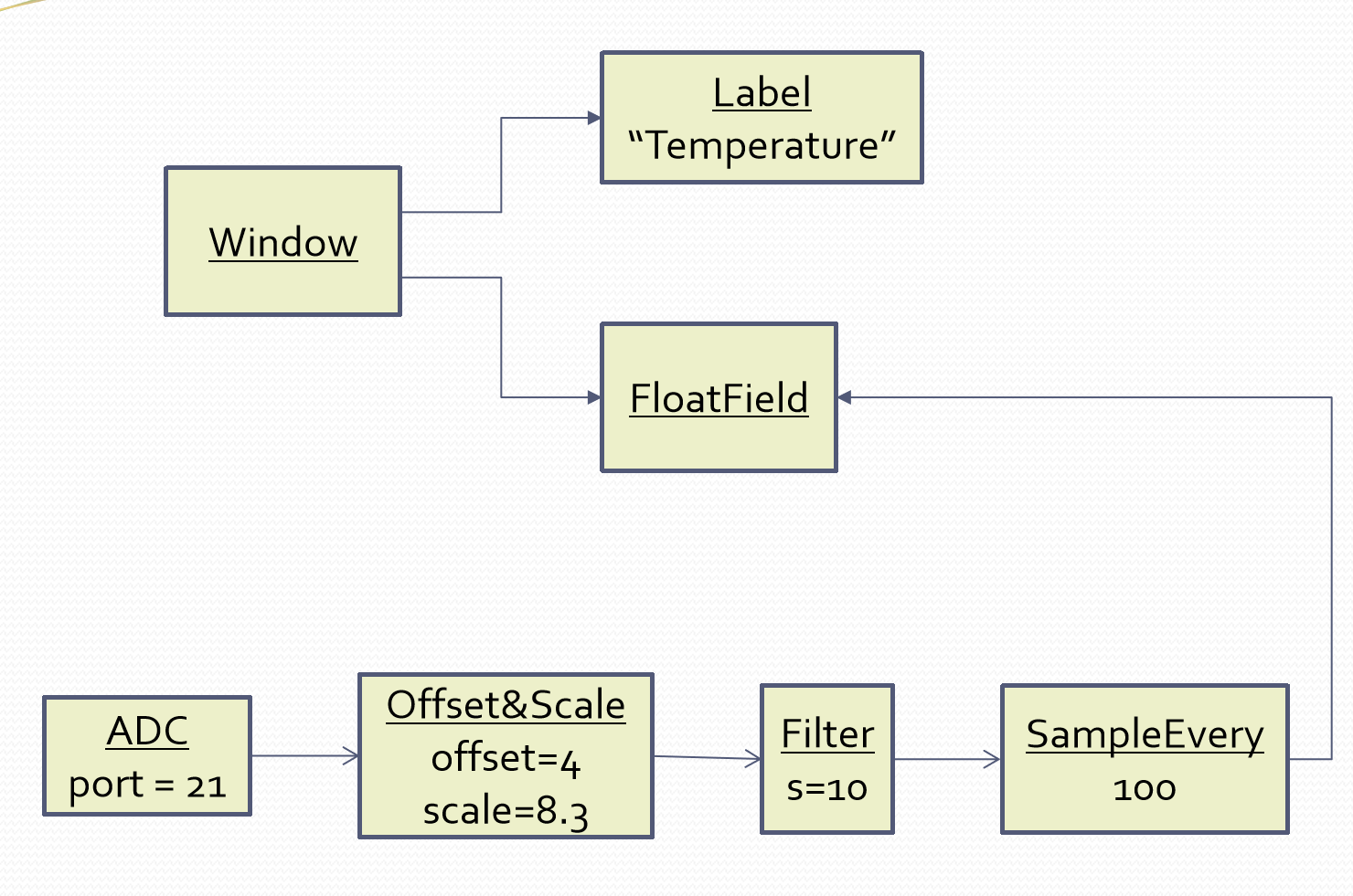
The diagram has both UI composition and dataflow composition. For the UI part of the composition, the lines obviously don’t mean dataflow - they mean 'display inside'. So now different lines in our diagram have different meanings. Here is how that diagram is represented as text.
 void main()
 {
    FloatField temperature;

    program = new ADC(channel=2)
        .WireIn(new Foreach())
        .wireIn(new OffsetAndScale(offset=4, slope=8.3))
        .wireIn(new Filter(10))
        .wireIn(new SampleEvery(100))
        .WireIn(new NumberToString()
        .wireIn(temperature = new FloatField());

    mainwindow = new Window()
       .wireTo(new Label("Temperture:"))
       .WireTo(temperature);

    mainwindow.Run();
 }
The text of the ALA thermometer has a symbolic connection for one of the wirings, "temperature". This is ok in this small program, but doing that won’t scale up. That is why we consider the diagram to be the source, and this text version is generated from it.
Looking once again at the diagram, you can see that ALA has allowed us to keep all cohesive knowledge about a thermometer together, and quite succinctly. It contains all the details needed to describe a thermometer, but does so in terms of domain abstractions that are not specific to a thermometer at all. There is no implementation in the application code. All implementation is done by domain abstractions. If you can see that point in the example code, then you are pretty much understanding ALA.
Once we have this diagram, it is easy to conceive how we might add features. For example, we could add two radio buttons into the UI, and wire then to a switcher abstraction that switches the data path between two instances of OffsetAndScale to change between Celcius and Faranheit.
2. Chapter two - The structure
In this chapter we describe the structure or anatomy of ALA without delving too much into the whys it is that way, which is covered in a later chapter.
The organisation of this chapter (and all chapters) is by different perspectives. We all have different prior knowledge on which we build new knowledge, so we each have a different way to understand new things. Use the section whose perspective makes the most sense to you. Because of the use of multiple perspectives, there will sometimes be repetition of ideas across the sections.
2.1. Software elements, relations among them
In this first perspective, we describe ALA in the context of one of the definitions of software architecture, "software elements and the relations among them". Indeed the first two fundamental constraints of ALA define what elements are and what their permisable relations are.
In this section, we also use an example code that lets us explain the concepts in a concrete way right down to the C# executable level. We show all the code in all the layers.
2.1.1. The only unit of code is an abstraction
The only unit of code in ALA is an abstraction. Not module, not class, not function. An abstraction may be implemented as a class or interface, (or multiple of them). But an abstraction is more than a module, class or function in that it must represent a 'generalized conceptual idea'. It’s what our brains use to understand the world, not what compilers use. It must be learnable as a concept. Many modules, classes or functions in traditional code are not good abstractions, especially if they are an integral part of a specific system with associations with peer modules, classes or functions.
Abstraction goes hand in hand with reuse. Krueger said that abstraction and reuse are two sides of the same coin. Abstractions tend to be stable - as stable as their conceptual idea. When we have a dependency on an abstraction, it is a dependency only on that conceptual idea.
Here is an example domain abstraction. It works on a stream of data. It smooths the data and slows down the rate. It has an input and an output dataflow port:
using ProgrammingParadigms;

namespace DomainAbstractions
{
    /// <summary> (6)
    /// ALA Domain abstraction.
    /// Has one DataFlow input port and one DataFlow output port, both type double.
    /// Smooths the incoming data and outputs it at a lower frequency.
    /// The strength parameter sets the degree of filtering
    /// (cutoff frequency relative to input frequency).
    /// and also sets the lower rate of output.
    /// e.g. if Strength is set to 10, then there is one output for every 10 input
    /// datas received.
    /// You need to understand the programming paradigm abstraction, IDataFlow,
    /// to understand this code.
    /// </summary>

    class LowPassFilter : IDataFlow<double> // input port (1)
    {
        public LowPassFilter(int strength, double initialOutput = 0.0) (3)
        {
            this.strength = strength;
            this.lastOutput = initialState;
        }

        private IDataFlow<double> output;  // output port (2)

        private int strength;
        private double lastOutput = 0.0; (4)
        private int resampleCounter = 0; (4)

        void IDataFlow<double>.Push(double data) (5)
        {
            lastOutput = (data + strength * lastOutput) / (strength+1);
            if (resampleCounter==0)
            {
                resampleCounter += strength;
                output?.Push(lastOutput);
            }
            resampleCounter--;
        }
    }
}| 1 | The input port, the implemented interface |
| 2 | The output port, simple private field of an interface type
The input port is the IDataFlow<double> interface that is implemented by the class. Dataflow is a programming paradigm which is a stream of data without end. Incoming data arrives via the Push method in this interface. We never know where the data comes from. The output port is the private field named "output". This field will be set pointing at an IDataFlow<double> input of an instance of another abstraction somewhere. We never know where the data goes to. How the output field gets set is described later. Because the abstraction uses ports, it has no knowledge of other peer abstractions. If it did, it would not be an abstraction. It is self-understandable at design-time, except for the even more abstract concepts on which it depends. In this case that is DataFlow and the concept of Wiring, which will wire instances of this abstraction to instances of other abstractions with compatible ports. These are described more fully shortly. |
| 3 | The public interface is only used by the layer above. It is only for creating and configuring instances of the abstraction. The abstraction has two configurations parameters. One is optional. Optional configurations can also be implemented with setters. |
| 4 | The abstraction keeps some internal state. This goes somewhat contrary to functional programming where we want all state to be passed in. In ALA a good abstraction trumps being stateless. As an abstraction that is naturally stateful, a filter should hide its state internally. |
| 5 | The implementation of the input interface does the work of the filter. Note that port interfaces are always implemented explicitly. (If implemented implicitly, they would be part of the public API of the class, which we don’t wan’t. We only want the port accessed via the interface.) |
| 6 | When an abstraction is created, it is critically important to add comments that make it learnable by explaining the concept it provides, its ports, its configurations and an example of its use. In Visual Studio, I copy these comments before the constructor because that allows them to pop up in the IDE when hovering on the constructor name where instances are created with a new keyword. |
In ALA, abstractions are implemented as files. The name of the file is the name of the abstraction. The file typically contains a class, but may contain more than one class, enums, delegates, interfaces etc. I usually put the implementation of the public configuration interface first, then the ports that are implemented as fields, then any other internal state, then the implementations of the ports.
Internally, abstractions are cohesive (which means sticking together) or highly interconnected code collaborating for a single purpose. Because it’s cohesive code, ALA does not prescribe any internal organisation for abstractions. We do not care about dependencies or any inter-relationships inside an abstraction. Any part of the code may need knowledge of any other part to understand. In fact the more cohesive everything is the better, as long as it is small.
Abstractions are the only mechanism that provides design-time information hiding. When David Parnas coined the term information hiding he meant at design-time. Unfortunately there is a popular meme that information hiding means encapsulation, which only hides at compile-time, not necessarily at design-time. The same idea of design-time information hiding has other names such as Alistair Cockburn’s protected variations, and Robert Martin’s version of the OCP (open closed principle).
In the case of our LowPassFilter, the quality of being a good abstraction means that its internals are not coupled or collaborating with other modules. It’s bounded by its conceptual idea. If it were a module instead, it might primarily perform the filter function for a specific application, but knowing which application it is part of may cause it to take on ancilliary functions, such as offset and scale to output the units needed by the application. Or it might grab its input knowing where it comes from. Or it might send it’s output to a specific place, or even to multiple specific places using direct method calls. It might connect to the application’s settings menu for its settings. All these things would cause design-time coupling through the application.
Meaning of abstraction
Unfortunately, there are now two distinct meanings for the meme 'higher level of abstraction' in common usage in software engineering. We need to take a moment to understand the difference. In ALA, abstraction means the original dictionary meaning:
The other meaning of 'higher level of abstraction' used in the software engineering community appears to be 'further away from the domain of the computer and closer to the problem domain'. For example, layers are often shown building up from the hardware. They can also build up from the database, or a physical communication medium, such as the layers of the OSI communications model. In this meaning, the application is considered the most abstract. For example, a 3-tier system or a communication stack uses this type of layering. The perception is that because we no longer have to deal with computer domain details such as data storage, communications protocols, hardware, etc, we must be more abstract. The problem with this is that the problem domain also deals with details. These details come from the real world and are described by detailed requirements. The modules that contain these details are no more abstract than those in the various domains of computing.
Conventional layering tends to use this second meaning of 'abstract' and layers are said to be more abstract as you go up. ALA layers get more abstract as you go down.
The layers are not the same either. To convert conventional layers to ALA, you generally just tip them on their side so that they are not layers but independent disconnected abstractions. Each of them knows about details of something but they no longer directly connect to each other in either direction. On their own they will do nothing. The layer above, whose job is to know the details of a specific application or system, composes instances of them by instantiating them, configuring them, and wiring them together using compositional abstractions in a lower layer. This top layer code is the least abstract, even though it only has knowledge of the requirements, and no knowledge from any 'computing' domain.
A final thought about abstraction is to compare it with the SRP (single responsibility principle). The SRP is not really the best way to think about abstractions. It is better to think about what details an abstraction implementation knows about. It can be a specific user story, a specific feature, a type of UI element, a type of database, a protocol, a hardware device, etc. It will contain all the cohesive knowledge about that thing. In doing so, it may have multiple responsibilities. For example an abstraction that knows about a protocol or a hardware device may have responsibility for both input and output. It may have responsibility for configuring the hardware device. A filter abstraction may both smooth the input data and resample it to a lower rate at the output, because resampling is cohesive with smoothing. So an abstraction is not necessarily a single responsibility. It is a single thing it knows all details about.
2.1.2. Abstraction internal structure
Internally an abstraction is cohesive. This means that every line of code is related to, and collaborates with, every other line of code to implement the idea of the abstraction. It has no internal structure imposed by ALA. It is essentially a small ball of mud.
We shouldn’t think of an abstraction implementation as being a composition of elements such as functions, variables, structs, methods, enums, delegates, statements, lines of code or the like because they are all collaborating. They are all just syntactical components, but not semantic components. In other words, they don’t have meaning on their own related to the concept of the abstraction. Only when we take all of lines of code together do we have meaning. So we never semantically break an abstraction implementation into smaller parts.
The external structure and internal structure with respect to abstractions are at opposite extremes. One is zero coupled and constrained only to the use of instances of lower layer abstractions and the other is fully coupled and highly cohesive.
That there is no structure in an abstraction’s implementation is important because in conventional architectures we are used to hierarchical encapsulation. In ALA there is no containment nesting at all. Instead there is only abstraction layers.
2.1.3. ALA uses only one relationship type
This is the second of the three fundamental constraints. ALA uses a single type of relationship - a dependency on an abstraction that is more abstract than the one whose implementation uses it.
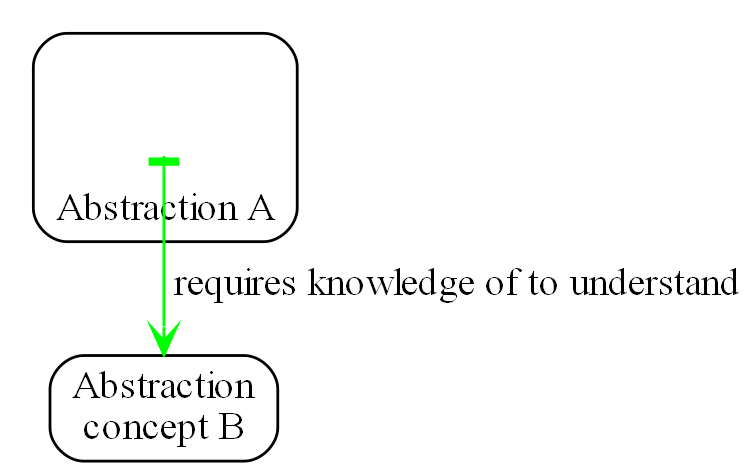
In terms of our previous example, LowPassFilter is Abstraction A and IDataFlow is Abstraction concept B.
Notice how in the diagram the relationship arrow comes from inside A. This is significant. It is the code that implements A that requires knowledge of abstraction concept B. We never actually draw lines when using abstractions, so you wont see this type of line in ALA diagrams. We only use it here while describing this one type of relationship that we are allowed.
B must be more abstract than A. "More abstract" means more general, not specific to A, and have a greater scope of reuse than A.
Because B is more abstract, it is more stable. ALA therefore automatically enforces the Stable Dependencies Principle.
The relationship means that, to read and understand the code inside A, you must know the abstraction concept B - not how the insides of abstraction B work. The word "abstraction" implies that it should be learnable in a short time and easy to retain. When we learn an abstraction concept, there is a moment when we suddenly 'get it', a small moment of insight.
In our A & B example above, the code inside B knows nothing of A. The code inside A, while it knows about the concept of the abstraction B, knows nothing about the code that is inside B. So there is zero coupling between the code that implements the two abstractions. ALA is basically a constraint to force us to always use zero coupling.
Here are some more legal dependencies, this time in text form. They are from a user story in the application layer to the domain abstractions layer.
    new AnalogInput(channel: 2)
    .WireIn(new LowPassFilter(strength: 10))
    .WireIn(new OffsetAndScale(offset: -31, scale: 0.2))
    .WireIn(new Display(label: "Temperature"));
Legal dependencies from a Thermometer user story abstraction on abstractions AnalogInput, LowPassFilter, OffsetAndScale, Display and WireIn. The user story takes input from an analog to digital converter, filters them to remove noise, scales them to be in degrees, and displays them.
Because of the way our brains have evolved to understand a complex world in terms of abstractions, abstractions are the only mechanism that hide knowledge at design-time. Dependencies on more abstract abstractions have zero coupling between the code using the abstraction and the code implementing the abstraction.
Dependencies on more abstract abstractions also explicitly tell us what knowledge we need in order to understand code. For example, if abstraction A is thermometer and abstraction B is display, then to understand the code that implements the thermometer requires knowledge of the concept of display. That’s why we sometimes refer to it as a knowledge dependency. Such a dependency always applies at design-time.
The dependency usually applies at compile-time and run-time as well, but not necessarily. It could be purely a knowledge dependency, for example a dependency may be on a convention, or it may be simply the knowledge of ALA. You need knowledge of those things to fully understand the code. We want to be explicit and clear about knowledge dependencies for every bit of code inside every abstraction, so we endeavour to always state implicit knowledge dependencies in comments. For example, in the implementation of an abstraction for a hardware device, I always include a reference to the datasheet.
Architectures generally work by applying constraints that restrict the infinite variety of ways code could be written. The ALA constraint of allowing a single relationship type may seem severe, but after some practice, it changes from a hinderence to being an increasingly helpful guide to the design. Sometimes the abstractions come easily from the wording in the requirements and sometimes they require a determined inventive thought process, especially in a new domain.
If you are finding it difficult, then first make sure you have well written requirements that capture all details. The user story abstractions should be just a more formal expression of them in terms of abstractions they probably already mention.
In most domains, I usually start with the UI description in the requirements as they most readily reveal their domain abstractions. Then it becomes apparent that dataflows must be connected to these instances of UI abstraction elements. Data transformation and state abstractions will become apparent next.
RIP the UML class diagram
All UML relationships except one are illegal in ALA, and that one is restricted to being a composition on a more abstract class or interface. Such a relationship is always represented in code by just referring to the abstraction by its name. For example, you wouldn’t use a library abstraction such as regex by drawing a line on a diagram to a box representing the regex class. You would just use the regex abstraction by name.
Furthermore, such a use of an abstraction by name is inside the class. It’s part of the class’s internal implementation. It makes no sense to show the relationship at the zoomed out scale outside the class with a filled diamond line coming from the border.
So, if a UML class diagram were drawn of an ALA application, there would be no lines at all, just boxes in space arranged in layers. This makes sense, because classes are used to implement abstractions, and abstractions have zero coupling with one another.

The diagram is not useful. We will never use it again. That’s not to say we won’t use diagrams. Diagrams can be used in ALA to represent the internals of an abstraction. This is often done in the layer representing the application or a feature or user story. In ALA terms, it shows instances of (lower layer) abstractions composed together as a graph. In implementation terms it is a (static) UML object diagram.
Class diagrams are evil. I think they have done more damage to software architecture than any other meme in our industry. Following are the UML relationships you cannot use in ALA, and what you do instead.
-
Association: A conventional program will typically have many bad dependencies referred to as associations in the UML. Most are there because data, messages, events, execution flow, etc, need to get from one place to another in the program. They are illegal in ALA. So how can a program work without them? How do we get data and events from one place to another at run-time? The short answer is that all these associations become a simple line of code inside an abstraction in the layer above. Such lines of code are not relationships or dependencies between the abstractions involved, they simply instantiate the abstractions involved. You create objects in a higher level abstraction and then wire them together. The abstractions themselves do not know where their data comes from, nor where it goes.
Note that simple dependency injection or otherwise passing an object into another object doesn’t remove the association between their respective classes. It only changes the relationship from composition to association, neither of which is allowed between peer classes. In other words, in ALA you are not allowed to know about a class in the same layer, not even its interface. Not even a base class. Instead you must use a much more abstract interface called a programming paradigm interface from a lower layer. The use of this type of interface means that the classes know nothing about each other. That’s why we call the usage a port.
-
Composition, Aggregation, Realization: Although the knowledge dependency relationship used in ALA can be implemented as a UML composition relationship (arrow with filled diamond), an Aggregation (arrow with unfilled diamond) or Realization (dashed arrow) the ALA knowledge dependency is more constrained. It must be instantiating a class, using objects of a class or interface, or implementing an interface in a lower, more abstract, layer. The composition, aggregation and realization relationships in ALA can go down by one or more layers, but never up or across within a layer.
-
Inheritance: ALA doesn’t need or use inheritance. It would break the abstraction of the (more abstract) base class in the lower layer. Instead we always use composition.
By way of example, given the concepts of vehicle, car and truck, in conventional object oriented programming we may be tempted to create a base vehicle class in a lower layer, and implement car and truck in the higher layer. But we may then be tempted to implement things that most vehicles have such as 4 wheels, and attempt to override that when we have an exception such as a vehicle with tracks.
If we restrict ourselves to composition, common parts of the vehicle domain would be invented as their own abstractions in the lower layer. We create multiple classes for these common parts as building blocks. Then we just compose car, track and tank from them.
In other words, the word, 'vehicle', would mean a category or domain, not a part in itself.
Now if we need to express the requirement to "drive the vehicle", car, truck and tank would each implement a 'drive' interface with, say, accelerate, slowdown, and steer methods, not be derived from a generic vehicle that is drivable. In the domain layer we may implement a behaviour class that implements general driving behaviour. Sych a Drive domain abstraction may have ports that are connectible to other domain components' ports such as engine control port, and brake control port.
To override the Drive domain abstraction’s behaviour, you would put code in the car, truck or tank application code where it uses the Drive object.
Most variations would be handled by a configuration interface (the public interface) on each domain abstraction.
If there was justification to build a concrete generic drivable vehicle, it would be used from the upper layers using composition not inheritance. It would likely have a lot of configuration. A real world example would be more like a chassis or platform concept. But this is probably a bad design as the chassis or platform concept would likely have many functions and so not be a good abstraction, would not be as versatile as composing it from parts, and would not be small enough in implementation.
Something inheritance provides is a mechanism for 'calling up the layers' at run-time through its virtual functions. In ALA, we do this with ordinary observer (publish/subscribe) pattern (events in C#), or by passing in a method as a configuration (usually anonymously or as a lambda expression), or by using the strategy pattern.
-
Packages: ALA does not use hierarchies or nesting. In other words, abstractions cannot be contained by other abstractions. Abstractions are never private. The reason they are never private is simple. An abstraction that is depended on should be more abstract than the abstraction using it. A more abstract abstraction needs to be public so it can be reused. ALA uses abstraction layers instead of encapsulation hierarchies. In ALA, packages would only be used as a distribution mechanism, not as part of the architecture for information hiding.
The word package means things packed together. Packages are usually just a grouping of abstractions such as a library. We should not consider knowledge dependencies to be on the package because we can’t generally learn a package. They are not abstraction in themselves. We should consider knowledge dependencies to be on the individual abstractions of the package.
Let’s consider a situation where a conventional package is a good abstraction in itself. Because it was implemented as a package, it’s internal implementation is large (Facade pattern). Let’s say our conventional package hides a lot of complex implementation and uses abstractions that we are not interested in using in the rest of our application. For example it could be a compiler that we can invoke from our application. The thing is, if the compiler abstraction is written using ALA, it will use lots of useful abstractions for the domain of compilers and parsing. We still want those abstractions to be public for reuse. It’s just that we don’t want them particularly visible to the rest of our application, which is in a different domain. To solve this problem we should still make the abstractions used by the compiler abstraction public, but put them into a different DomainAbstractions folder and namespace. When we do this, we will want the DomainAbstractions folders to be qualified with the name of the domain, such as CompilerDomainAbstractions.
-
Namespaces: While not part of the UML, we can discuss namespaces here in case you think of them in some way similar to packeages. In ALA, namespaces are used for the layers. For example we use namespaces such as Application, DomainAbstractions and ProgrammingParadigms. This allows unrelated abstractions in different layers to have the same name. The files that implement abstractions are put inside folders that have the same names as the namespaces.
Note that unlike packages, namespaces are not encapsulations. Namespaces only make names unique. One 3rd party tool I used to generate dependency graphs showed dependencies on namespaces as if namespaces were encapsulations. This gave a completely misleading view of the true nature of the dependencies in the code. I had to write a custom query for the tool to show the actual dependencies on the abstractions inside the namespaces.
2.2. Abstraction layers
In this perspective, we look at the structure of ALA in terms of layers. This is the perspective that gives Abstraction Layered Architecture its name, and its the one we should have in mind when organising our ALA code.
Because the target of a dependency must be more abstract, abstractions naturally arrange themselves in discrete layers. In implementation, each layer should have its own folder under the parent project folder.
Only a small number of layers are needed. Consider that we can construct the human body with just six abstraction layers: Atoms, Molecules, Proteins, Cells, Organs, Body. Probably need another two layers to build the human brain (an organ) from neurons (which are cells) according to the internal structure of the brain, which I don’t know. Small applications generally use four layers. The layers are given standard names that describe their level of abstraction:
These layers are not fixed by ALA. But we tend to return to these ones in our experience so far. Following is discussion of each layer together with example code to see how everything works.
Application layer
In describing example layers, we start with some code. This code will build into a complete running application so no holes are left in understanding how everything works. The accompanying bullet points then explain the organisation of the code in the layers. The code is available here: https://github.com/johnspray74/Thermometer
using DomainAbstractions;
using ProgrammingParadigms;
using Foundation;

namespace Application
{
    class Thermometer
    {
        public static void Main()
        {
            Console.WriteLine("Wiring application");

            private ADCSimulator adc;

            adc = new ADCSimulator(channel: 2, period: 1000) { simulatedLevel = 400 }; (1)
            adc.WireIn(new LowPassFilter(strength: 10)) (2) (5) (6)
                .WireIn(new OffsetAndScale(offset: -200, scale: 0.2)) (3)
                .WireIn(new DisplayNumeric<double>(label: "Temperature") { units = "C"} ); (4)

            Console.WriteLine("Running application");
            adc.Run(); (7)

            Console.WriteLine("press any key to stop");
            Console.ReadKey();
        }
    }
}
To understand ALA code, you need to have knowledge of the abstraction concepts it uses. In this top layer code, these are:
| 1 | ADCSimulator - domain abstraction simulates an analog to digital converter hardware peripheral. Has a single output port of type IDataFlow<int> |
| 2 | LowPassFilter - domain abstraction - we already met this at the beginning of this chapter. Has input and output ports of type IDataFlow<double>. |
| 3 | OffsetAndScale - domain abstraction - has a single input port and a single output port, both IDataFlow<double>. Adds a constant and Multiplies by another constant to transform data like a straight line on an x-y graph. |
| 4 | DisplayNumeric - domain abstraction - has one input port of type IDataFlow<double>. Displays the value on the console with label and optional units. |
| 5 | WireIn - foundation abstraction - wires compatible ports of instances of abstractions by setting the private field in the first object that matches the interface implemented by the second object. |
| 6 | These wirings are using the Dataflow programming paradigm. Dataflow is used by the ports of the domain abstractions and allows their instances to push data from one to the next at runtime if they are wired together. For dataflow programming, we default to pushing data through the system (from ADC to display). We use pulling when there is good reason, usually for performance. |
| 7 | The adc, which is the source of the data that gets pushed through the system, needs to be told to start running. |
Once you have knowledge of these abstractions, notice that the application code is readabable by itself. That knowledge sits at the abstraction level of the requirements. It is highly cohesive - every line works together with every other line to make a thermometer. This abstraction holds all knowledge about thermometers. There is no code anywhere else that has anything specific to do with thermometers. It does none of the work itself - it just assembles and configures instances of the the needed domain abstractions.
The application layer is three things in one: The architecture design, the expression of requirements, and the executable. In conventional software development, these are three separate artefacts.
Execution typically occurs in two phases (similar to some monads). In the first phase the application wires together instances of abstractions. In the second phase the network of instances executes (which is what the finalizing call to Run starts).
Domain abstractions layer
At the beginning of this chapter we had an example of a domain abstraction, LowPassFilter. Here is another example:
using ProgrammingParadigms;

namespace DomainAbstractions
{
    /// <summary> (1)
    /// ALA domain abstraction
    /// Has one input port of type IDataflow and one output port of type IDataflow
    /// (both type double)
    /// Performs y = m(x+c) like operation where x is the input and y is the output
    /// If visualized as a straight line on an x,y graph, -c is the x axis intercept
    /// and m is the slope.
    /// You need to understand the programming paradigm abstraction, IDataFlow,
    /// to understand this code.
    /// </summary>
    class OffsetAndScale : IDataFlow<double> // input (2)
    {
        public OffsetAndScale(double offset, double scale) (4)
        {
            this.offset = offset;
            this.scale = scale;
        }

        private double offset;
        private double scale;


        private IDataFlow<double> output; (3)

        void IDataFlow<double>.Push(double data) (5)
        {
            output.Push((data + offset) * scale);
        }
    }
}
Notes on the code:
| 1 | Important to say what the abstraction concept is in the comment section. |
| 2 | The input port is the implemented interface.
In the application code in the top layer, an instance of LowPassFilter was wired to an instance of OffsetAndScale. When wired, the output field of the LowPassFilter is set to the OffsetAndScale object, cast as the appropriate interface, in this case IDataFlow<double>. |
| 3 | The output port output is private so that it does not appear as a part of the configuration interface to the layer above. It is set by WireIn or WireTo using reflection. |
| 4 | It has two compulsory configuration parameters. |
| 5 | When data arrives at the input port, it is transformed and pushed out of the output port. |
For completeness, here are the other two domain abstractions that we used in the Thermometer application example:
using ProgrammingParadigms;

namespace DomainAbstractions
{
    /// <summary>
    /// ALA Domain Abstraction
    /// Ouptuts incoming data to the console with a preceding label and optional units.
    /// Has one input port of type IDataFlow which can take int, float, double
    /// The label must be passed in the constructor.
    /// The units property may be used to set the units.
    /// fixPoint Property sets the number of decimal places.
    /// You need to understand the programming paradigm abstraction, IDataFlow,
    /// to understand this code.
    /// </summary>
    class DisplayNumeric<T> : IDataFlow<T>
    {
        public DisplayNumeric(string label)
        {
            this.label = label;
        }

        public int fixPoints { get; set; } = 0;

        private string label;
        public string units { get; set; }


        void IDataFlow<T>.Push(T data)
        {
            double d = (double)Convert.ChangeType(data, typeof(double));
            Console.WriteLine($"{label}: { d.ToString($"F{fixPoints}") } {units}");
        }
    }
}using ProgrammingParadigms;
namespace DomainAbstractions
{
/// <summary>
/// ALA Domain Abstraction.
/// Simulate a 10-bit ADC (analog to digital converter).
/// Normally an ADC is a hardware peripheral, but here we just do a software
/// simulation of one to use as a source of data for example applications.
/// A real ADC driver would have properties for setting the channel and period.
/// You would create one instance of this driver for each ADC channel.
/// It would output raw data in adc counts.
/// Since it is a 10 bit ADC, the adc counts are in the range 0-1023.
/// We retain the channel although it is not used by the simulated version.
/// The simulated version has two simulation properties, one to set the simulated
/// ADC reading.
/// and one to set the level of noise in the simulated readings.
/// You need to understand the programming paradigm abstraction, IDataFlow,
/// to understand this code.
/// </summary>
class ADCSimulator
{
public ADCSimulator(int channel, int period = 100)
{
this.channel = channel;
this.period = period;
}
private int channel; // unused on simulated ADC
private int period; // milliseconds
public int simulatedLevel { get; set; } = 512; // 0 to 1023
public int simulatedNoise { get; set; } = 0; // 0 to 1023
private IDataFlow<int> output;
public void Run()
{
RunAsyncCatch();
}
public async Task RunAsyncCatch()
{
// because we are the outermost async method, if we let exceptions go,
// they will be lost
try
{
await RunAsync();
}
catch (Exception ex)
{
Console.WriteLine(ex);
}
}
Random randomNumberGenerator = new Random();
public async Task RunAsync()
{
while (true)
{
// add a bit of noise to the adc readings
int data = simulatedLevel + randomNumberGenerator.Next(simulatedNoise)
- simulatedNoise/2;
if (data < 0) data = 0;
if (data > 1023) data = 1023;
output.Push(data);
// throw new Exception("exception test");
await Task.Delay(period);
}
}
}
}Note that the output port of ADCSimulator is IDataFlow<int>, and the application wired it directly to a LowPassFilter whose input port was type IDataFlow<double>. So we should have wired a type converter abstraction inbetween. We’ll do that in a later example.
As can be seen in the above examples, the domain abstractions layer contains abstractions that can be composed into applications. These are typically building blocks for I/O, data transformations, and persistent state, but many other types of abstractions are possible.
It’s important that these domain abstraction no nothing about the thermometer. They are not specifically parts of a thermometer. Even though in our example, an instance of an ADC is composed with an instance of a LowPassFilter, the ADC and the LowPassFilter don’t know who they are going to be wired to. They could be wired to anything that will give them data or take their data. They only know as far as their own ports, not beyond that.
Some of these types of abstractions may also be found in general language libraries but domain abstractions are more specific to the types of applications we want to express using them. They are specific to a domain, making them more expressive, but less reusable than general purpose library abstractions. They are still reusable both within a single application and by other applications in the same domain.
Another difference between ALA domain abstractions and typical library abstractions is the use of ports. This supports building functionality by simply composing instances of abstractions. While the higher layer composing code controls who will communicate with whom, it does not actually handle the data at run-time. The data moves directly between instances via the wired ports. Library abstractions typically don’t use ports. So the composing code typically has to handle the data. They will pass data to the library abstraction instance, and receive data back.
A further difference between ALA domain abstractions and typical library abstractions is that when domain abstractions are composed, the meaning of composition can be a programming paradigm other than imperative. For example the application above uses a dataflow programming paradigm. Imperative is not usually a good programming paradigm for the expression of requirements, but it’s all your basic language and library gives you (unless you are using language integrated monads, which also give you dataflow programming). But ports allow you to use any kind of programming paradigm. For example, we can make ports that when wired mean laying out a user interface. That is, wiring these types of ports means putting a UI element inside another UI element on the display.
The domain abstractions layer and programming paradigms layer together are like a DSL (Domain Specific Language). We can think of domain abstractions as composable elements and the programming paradigms as the grammar.
The domain and programming paradigm layers are an internal DSL (as appossed to an external DSL). This means that they only use the underlying language (WireTo is an extension method, and new is a language keyword). They don’t introduce any new syntax outside of the underlying language that would need parsing. This allows you to easily fall back on the greater flexibility of the underlying language when you need to. For example, when configuring a domain abstraction, you could pass in lambda expressions. Or, you can pass a whole object of a class that you write in the application layer (which is the strategy pattern).
Conventional libraries generally contain good abstractions. What makes them good abstractions is that their designers don’t know anything about the specific applications that will use them. Writing domain abstractions is best done in the same way. After the need for an abstraction is decided, pretend you don’t know anything about the application, and are writing something to be useful, reusable and learnable as a new concept. Then they should not just be specific parts of a specific application, but concepts that you can learn so that when you read that code that uses them, you don’t have to go and read the implementation.
As we said, abstractions know nothing of each other at design-time, yet can still communicate directly with one another at run-time. It is the responsibility of the code in the layer above that composes them to know the meaning of the data. It knows the meaning of the data even though it does not handle the data. For example, our application above knows that data going from the ADC to the LowPassFilter is raw adc values representing temperature, and what the values mean. It knows that the data passing between the LowPassFilter and the OffsetAndScale is sufficiently smoothed and slowed down for a stable display. It knows that the data passing from the OffsetAndScale to the display is in degrees Celsius. All these pieces of knowledge are cohesive in the design of the thermometer, and are contained together inside the Thermometer abstraction. In a conventional application, these pieces of knowledge would likely be spread between multiple cooperating modules.
Programming paradigms layer
For the Thermometer example application above, we wired four instances of domain abstractions. That wiring used a single programming paradigm, Dataflow. Here is the interface for the dataflow programming paradigm:
namespace ProgrammingParadigms
{
    interface IDataFlow<T>
    {
        void Push(T data);
    }
}
Programming paradigm interfaces are often this simple. Another example programming paradigm is synchronous event driven. The corresponding interface might be:
namespace ProgrammingParadigms
{
    interface IEvent { void Execute(); }
}
Here is the interface for another common programming paradigm, the UI layout. In this programming paradigm, a parent UI element is wired to its contained child elements.
namespace ProgrammingParadigms
{
    interface IUI { UIElement GetUIElement(); }
}
The interface returns the .NET WPF element of the child. This allows domain abstractions to construct the UI using underlying WPF elements. In effect, UI domain abstractions are wired together in a similar way to XAML. Both have descriptive, tree structured syntax, but ALA is using the underlying C# language whereas XAML is using XML.
You can conceive other programming paradigms to give different meanings to composition of domain abstractions in such a way as to allow the easiest representation of typical requirements. For example, for implementing game scoring, I used a programming paradigm called ConsistsOf. For tennis, I used it to express that a Match consists of Sets, a Set consists of Games, and a Game consists of Points. See the example project at the end of chapter four which uses it to implement both tennis and bowling scoring programs. Being able to compose instances of domain abstractions together with meanings that you define in the programming paradigms layer is a powerful way to express requirements succinctly.
ALA is polyglot in programming paradigms. An application typically mixes a small set of different paradigms. Each provides a different meaning when the application wires two instances of domain abstractions together. Examples might be Dataflow, UI Layout, Event driven, State machine transition, Data schema entity relationship. Some may have variations such as pushing or pulling, or synchronous and asynchronous.
Programming paradigms provide the execution mechanism of direct communication between instances of domain abstractions. They do this without the abstractions themselves knowing anything about each other. This means that it is the programming paradigms that control the whole way the application actually executes. Neither the Application layer, nor the domain abstractions layer are involved in this. The application layer is just composing domain abstractions. The domain abstractions only respond to what happens at their ports.
Execution models such as synchronous vs asynchronous, push vs pull, and fan-out and fan-in wiring are discussed in Chapter four.
Programming paradigms provide the rules for the way instances of domain abstractions can be composed by the application. They are the grammar of the DSL.
Through the use of programming paradigms, domain abstractions know nothing about each other at design-time, yet instances of them can communicate at run-time. Of course we could achieve this by making the application handle the run-time communications. The common example would be an application that calls one function which returns a result, and then calls another function passing the result to it. This would almost comply with ALA. The problem is we don’t really want the application to be concerned with run-time communications. The application really just wants to concentrate on representing user stories by composing instances of domain abstractions. So we use a layer below the domain abstractions called programming paradigms. The programming paradigms allow domain abstractions to have compatible ports, which in turn allows them to communicate directly with one another at run-time. The design of the specific communications that will take place is in the Application layer, but all the execution is in the domain abstractions and programming paradigms layers.
Foundation layer
The foundation layer contains code used to support ALA programs in general.
A common pattern I use is a WireIn() and a WireTo() extension method in the foundation layer. The application layer uses them to wire together instances of Domain Abstractions using ports.
WireIn() and WireTo() are dependency injection methods, but ALA is more constrained than your average application implemented on dependency injection, because the interfaces used must be more abstract than the domain abstractions whose instances are being wired together.
WireTo(), uses reflection. It’s not essential to use reflection for ALA. You could use dependency injection setters in every domain abstraction instead. You would need one setter per port on the left abstraction. You wouldn’t use constructor dependency injection because sometimes wiring a port is optional. I prefer using the WireTo extension method because it allows domain abstractions to not need all these setter methods.
Here is minimal code for the WireTo method in case you are interested to see how the reflection works. It not necessary to understand this code to use ALA.
Wiring.cs
namespace Foundation
{
    public static class Wiring
    {
        /// WireTo is an extension method on the type object.
        /// Wires instances of classes that have ports by matching interfaces.
        /// Port name can be optionally provided for the A side.
        /// If object A has a private field of type interface,
        /// and object B implements that interface,
        /// and the private field is not yet assigned,
        /// assigns B to the field in A.
        /// Uses reflection.
        /// Returns the left object for fluent style programming.
        public static T WireTo<T>(this T A, object B, string APortName = null)
        {
            // achieve the following via reflection
            // A.field = B;
            // if 1) field is private
            //    2) field type matches one of the implemented interfaces of B
            //    3) field is not yet assigned

            if (A == null) throw new ArgumentException("A is null "); (4)
            if (B == null) throw new ArgumentException("B is null ");

            bool wired = false;
            var BType = B.GetType(); (1)
            var AfieldInfos = A.GetType().GetFields(System.Reflection.BindingFlags.NonPublic
                | System.Reflection.BindingFlags.Instance)
                .Where(f => (APortName == null || f.Name == APortName)) // match portname if any
                .Where(f => f.GetValue(A) == null) // not yet assigned
            var BinterfaceTypes = BType.GetInterfaces().ToList(); // ToList to do the reflection once

            foreach (var AfieldInfo in AfieldInfos) (2)
            {
                var BimplementedInterface = BinterfaceTypes
                    .FirstOrDefault(interfaceType => AfieldInfo.FieldType == interfaceType);
                if (BimplementedInterface != null)  // there is a matching interface
                {
                    AfieldInfo.SetValue(A, B);  // do the wiring (3)
                    wired = true;
                    break;
                }
            }

            if (!wired) // throw exception (4)
            {
                var AinstanceName = A.GetType().GetProperties()
                    .FirstOrDefault(f => f.Name == "InstanceName")?.GetValue(A);
                var BinstanceName = B.GetType().GetProperties()
                    .FirstOrDefault(f => f.Name == "InstanceName")?.GetValue(B);

                if (APortName != null)
                {
                    // a specific port was specified - see if the port was already wired
                    var AfieldInfo = AfieldInfos.FirstOrDefault();
                    if (AfieldInfo?.GetValue(A) != null)
                        throw new Exception($"Port already wired  {A.GetType().Name}[{AinstanceName}].{APortName} to {BType.Name}[{BinstanceName}]"
                    );
                }
                throw new Exception($"Failed to wire {A.GetType().Name}[{AinstanceName}].\"{APortName}\" to {BType.Name}[{BinstanceName}]");
            }
            return A;
        }


        /// Same as WireTo, but returns the right object instead of the left object
        public static object WireIn<T>(this T A, object B, string APortName = null)
        {
            WireTo(A, B, APortName);
            return B;
        }
    }
}| 1 | It first gets an IEnumerable of all the private fields in class A. If a port name is passed in, it must match. Then it gets a list of all the interfaces of class B. |
| 2 | It iterates through the fields to find one that matches any of the interfaces of B. |
| 3 | It sets the field in A pointing to B, cast as the interface type. |
| 4 | When there are errors in wiring code, it would be nice to get errors at compile-time. The WireTo extension method can’t do that, but it does throw exceptions at wiring time when the application first starts. Since in ALA all wiring is generally done at this time, at least you wont have potential exceptions later during normal run-time. |
Four different exceptions may be thrown. 1) Object A (left object being wired) is null. 2) Object B (right object being wired) is null. 3) A specific A side port was specified, but it is already wired. 4) No matching A side port was found.
Once again, slightly more complete code is available here: https://github.com/johnspray74/Thermometer
Extra layer for larger applications
If a single abstraction is used for the application, then as more and more user stories are added into it, it will eventually get too large for the ALA size constraint. Meanwhile, domain abstractions and programming paradigms are stable and do not generally grow larger with overall program size. They may increase in number, but it is the application that will go over the 500 line complexity limit.
ALA will need to be applied to the large application abstraction by adding a new layer below it. The requirements are likely already written in terms of naturally separate abstractions which we call features or user stories. We can use these abstractions as the basis for the new layer. We call the layer "Features" or "User Stories". The application abstraction becomes a composition of features or user stories.
Let’s change the Thermometer example application we used above to have a new feature for measuring load as well as temperature. At the same time, let’s introduce a features layer with the two features: temperature and loadcell.
I have deliberately retained a need for communication between the two features to show how features can also have ports and be wired together.
Application layer
using Features;
using Foundation;

namespace Application
{
    class Application
    {
        /// <summary>
        /// Instantiate two features: a temperature readout and a loadcel readout.
        /// Also wire the Temperature to the Loadcell for temperature compensation
        /// </summary>
        public static void Main()
        {
            Console.WriteLine("Wiring application features");

            var temperature = new Temperature(); (1)
            var load = new LoadCell(); (1)

            temperature.WireTo(load); // for temperature compensation (2)

            Console.WriteLine("Running application");
            Console.WriteLine("press any key to stop");
            temperature.Run();
            load.Run();
            Console.ReadKey();
        }
    }

}| 1 | The code instantiates two features for this particular application. |
| 2 | The code wires together the feature to get temperatures sent to Loadcell at run-time. Feature abstractions can have ports. A common example of wiring between features would be to wire a feature instance’s menu items to a main menu feature. |
Features layer
The Features layer contains independent features or user story abstractions.
Each feature creates instances of domain abstractions, configures the instances with feature specific details, and connects them together as needed to express the feature or user story.
Here is the Thermometer application rewritten to be a Temperature feature. It has been modified to output the temperature in Celsius to a port. This port can be wired to any other features that want to know the temperature:
using DomainAbstractions;
using ProgrammingParadigms;
using Foundation;

namespace Features
{
    /// <summary>
    /// Feature to coninuously measure temperature and periodically display it
    /// in degrees C on the console.
    /// Has an output port that outputs the temperature.
    /// </summary>
    class Temperature
    {
        private IDataFlow<double> output; // temperature in celcius (1)

        private ADCSimulator adc;

        public Temperature()
        {
            const int adcLevel = 400;  // 40 C
            adc = new ADCSimulator(channel: 2, period: 1000) { simulatedLevel = adcLevel, simulatedNoise = 100 };
            adc.WireIn(new ChangeType<int, double>()) (2)
                .WireIn(new LowPassFilter(strength: 10, initialState: adcLevel))
                .WireIn(new OffsetAndScale(offset: -200, scale: 0.2)) // 200 adc counts is 0 C, 300 adc counts is 20 C
                .WireIn(new DataFlowFanout<double>()) (3)
                .WireTo(new DisplayNumeric<double>(label: "Temperature") { units = "C"} ) (5)
                .WireTo(new ToLambda<double>((d) => output?.Push(d))); (4)
        }


        public void Run()
        {
            adc.Run();
        }
    }
}| 1 | The feature has an output port for temperature
The wiring itself is the same as it was in the Thermometer application except that three extra objects are used to make the dataflow wiring work. Their classes come from the Dataflow programming paradigm abstraction. These classes are: |
| 2 | ChangeType: allows Dataflow ports of one type to be wired to Dataflow ports of a different type. In this case, the output of ADCSimlator is int and the input of LowPassFilter is double. (Remember in our Thermometer example application, we left this out, which was a problem, but now we have fixed it.) |
| 3 | DataFlowFanout: A normal output port can only be wired once. DataFlowFanout allows you to wire to multiple places. In this case we wanted to wire the output of OffsetAndScale to both a DisplayNumeric and an external port. |
| 4 | ToLambda. We want to wire the output of the DataFlowFanout to the our own port, output. You might think you could just write .WireTo(output). This almost works. The reason it doesn’t work is that when the Temperature constructor runs, the application code in the layer above is instantiating a Temperature object. That code would not have wired our the temperature object’s output port yet. It’s value will be null at this time. Therefore WireTo(output) would try to wire to null instead of some object. Therefore we instead wire to a simple intermediate object that will pass it’s input on to the Temperature classes output port at run-time. This intermediate object is from a domain abstraction class called ToLambda that simply has a single input port, and takes a function as its configuration. For the function we pass in a lambda expression that will push the data via the output port. |
| 5 | Note that WireTo is used to wire DataFlowFanout to multiple places. WireIn wires things in a chain. |
Here is the other feature used by our example application, the Loadcell.
using DomainAbstractions;
using ProgrammingParadigms;
using Foundation;

namespace Features
{
    /// <summary>
    /// Class:
    /// Feature to coninuously measure a load from a load cell and display it in kg on the console.
    /// Displays with one decimal place.
    /// Has temperature compensation for better accuracy (optionally feed temperature into the input port in degress C)
    /// </summary>
    class LoadCell : IDataFlow<double> // input for temperature compensation (1)
    {
        private ADCSimulator adc;
        private DataFlowInitializer<double> defaultTemperature;
        private OffsetAndScale offsetAndScaleTemperature;

        /// <summary>
        /// Constructor:
        /// Feature to continuously measure a load from a load cell and display it in kg /// on the console.
        /// Displays with one decimal place.
        /// Has temperature compensation for better accuracy (optionally feed temperature
        /// into the input port in degress C)
        /// </summary>
        public LoadCell()
        {
            // Wire an adc to an OffsetAndScale to an Add to a DislayNumeric.
            adc = new ADCSimulator(channel: 3, period: 500) { simulatedLevel = 200, simulatedNoise = 0 }; (2)
            var add = new Add(); (4)
            adc.WireIn(new ChangeType<int, double>())
                .WireIn(new OffsetAndScale(offset: 0, scale: 0.5)) (2)
                //.WireIn(new DataFlowDebugOutput<double>((s)=> System.Diagnostics.Debug.WriteLine(s))) (3)
                // .WireIn(new DataFlowDebugOutput<double>(Console.WriteLine)) (3)
                .WireIn(add)
                .WireTo(new DisplayNumeric<double>(label: "Load") { fixPoints = 1, units = "kg" } ); (2)

            // Wire the input port for temperature to another OffsetAndScale to the other input of the Add.
            defaultTemperature = new DataFlowInitializer<double>(); (6)
            offsetAndScaleTemperature = new OffsetAndScale(offset: -20, scale: -0.1); // compensate -0.1 kg/C from 20 C (2)
            defaultTemperature.WireIn(offsetAndScaleTemperature) (7)
                .WireIn(new DataFlowConvert<double, Double2>((d)=>new Double2(d))) (5)
                .WireIn(add);

        }


        void IDataFlow<double>.Push(double data)
        {
            ((IDataFlow<double>)offsetAndScaleTemperature).Push(data); (7)
        }


        public void Run()
        {
            defaultTemperature.Push(20);  // in case no temperture is connected to the input port, set it to 20 C
            adc.Run();
        }
    }
}| 1 | This time the feature has an input port for temperature, which is the implemented interface. |
| 2 | Notice the reuse of several domain abstractions in this feature. The DisplayNumber abstraction is configured to display one decimal place. |
| 3 | Debugging a dataflow can be done by inserting an object (decorator pattern) that outputs the values in the stream to a console output. |
| 4 | A new domain abstraction called Add is used. It has two IDataflow<double> inputs and a IDataFflow<double> output. We assign the Add to a local variable so that we can wire the second input later. Note that a C# class cannot implement the same interface twice (even though there is no reason why not). There are several ways we have used to work around this limitation. The one used here is to make one of the ports a Double2, a struct containing a double. This allows to have a double with a different type to the compiler, but the same type to us. |
| 5 | To wire to the Double2 input port, we convert from double to Double2 using a DataFlowConvert<double, Double2>() abstraction. This abstraction can do any transformation on Dataflow, so is analogous to the Select() or Map() functions used in query languages. |
| 6 | DataFlow initializer is a domain abstraction that can be used to initialize inputs of a dataflow in case no input arrives at run-time. In this case one of the two inputs to Add may not arrive if the temperature input port is not connected to anything. We therefore want to initialize it with a default temperature of 20 C. |
| 7 | Note that it is not a problem to do fan-in wiring. Both defaultTemperature and the input port are connected to the input port of offsetAndScaleTemperature. |
For completeness, here is the code for the Add domain abstraction. Note that this abstraction is doing more than what a single + operator would. It is adding two dataflows.
using System;
using ProgrammingParadigms;

namespace DomainAbstractions
{
    /// <summary>
    /// ALA domain abstraction to add two numeric dataflows.
    /// Currently only supports doubles.
    /// Two input ports are implemented interfaces.
    /// One output port called "output".
    /// Both inputs must receive at least one data before output begins.
    /// Thereafter output occurs when either input receives data.
    /// One of the inputs is type Double2, which is a struct containing a double.
    /// This is a work around for can't implement the same interface twice.
    /// When wiring to the Double2 port, do it via an instance of DataFlowConvert like this:
    /// .WireIn(new DataFlowConvert<double, Double2>((d)=>new Double2(d))).WireIn(new Add());
    /// You need to understand the programming paradigm abstraction, IDataFlow,
    /// to understand this code.
    /// </summary>
    class Add : IDataFlow<double>, IDataFlow<Double2> (1)
    {
        private IDataFlow<double> output; (2)

        private double? operand1; (3)
        private double? operand2; (3)

        void IDataFlow<double>.Push(double data) (4)
        {
            operand1 = data;
            if (operand2.HasValue)
            {
                output.Push(operand1.Value + operand2.Value);
            }
        }

        void IDataFlow<Double2>.Push(Double2 data) (5)
        {
            operand2 = data.Value;
            if (operand1.HasValue)
            {
                output.Push(operand1.Value + operand2.Value);
            }
        }
    }


    /// <summary>
    /// Wrap a double in a struct.
    /// We do this only to get a different type of double to effectively get multple inputs
    /// for the "Add" class because C# wont allow implementing the same interface
    /// twice (it should though).
    /// </summary>
    struct Double2
    {
        public Double2(double value) { this.value = value; }
        private readonly double value;
        public double Value { get { return value; } }
        public override string ToString() => $"{value}";
}| 1 | Two input ports |
| 2 | One output port |
| 3 | For storing the last value received on each input. They are nullables so that we know when we have had input. |
| 4 | Implement the first input port |
| 5 | Implement the second input port |
That completes our code example of an application that includes a Features layer. The application layer instantiated two feature abstractions, and wired one to the other. Each feature used several abstractions from the domain abstractions layer. Both the Features layer abstractions and the Domain abstractions used ports of type DataFlow.
2.3. Folders, files, classes, objects, interfaces, functions
This is the second perspective on ALA. In this perspective we look at the implementation language elements and see how they are used in ALA applications.
2.3.1. folders and namespaces
If you see an ALA application, you will find three to five folders that correspond with abstraction layers (described in the previous section). For example:
-
Application
-
Features
-
DomainAbstractions
-
ProgrammingParadigms
-
Foundation
Knowledge dependencies only go down these layers. So to understand the code inside files in the higher layers, you need to have knowledge of what all the files in lower layers do. There are no dependencies between files in any folder.
Namespaces exactly correspond with these folder names. Therefore we have namespaces called "Application", "DomainAbstractions", "ProgrammingParadigms", etc. This tells us which layer an abstraction comes from, and which folder it resides in.
Namespaces also avoid naming conflicts between layers. They are not useful beyond that. Unfortunately, there is no convenient way of telling the compiler or the IDE to not 'see' classes, interfaces etc in other files in the same namespace or folder.
2.3.2. Files
Abstractions are implemented as files. Abstractions are often implemented as a single class, function, or interface, but sometimes an abstraction consists of a small cohesive group of them, with things like delegates, enums, or even variables. Internal to an abstraction, they interconnect with each other unconstrained. There are no dependency rules inside a file. The only constraint ALA makes is that the total must be small - of the order of 200-500 lines of code, or under the brain size limit. This applies to all abstractions, including the ones that make up the application itself in the top layer.
In time I hope languages catch up and give us visibility support for ALA abstraction. This would probably involve a new construct called Abstraction{} to group the elements of an abstraction. It does not need a name. This construct replaces the use of a file that we are currently using as a stand-in. Anything public inside the Abstraction is only visible to code in higher layer abstractions, i.e. abstractions in higher namespaces. It is not visible in your own namespace, nor to those of lower layers. The compiler would need to know the namespace layering order. If we had this, we would have compiler checking for illegal dependencies.
2.3.3. Objects
In ALA, abstractions are usually a single class. Instances of such abstractions are objects. It is the objects that get wired togther by their ports. Classes are the design artefacts that know nothing about one another. Objects are the run-time artefacts that communicate with one another at run-time.
2.3.4. Interfaces
Classes have a 'main interface', the constructors, and any public methods and properties. A class can also implement other interfaces. In ALA, a class’s 'main interface' (it’s constructors and public methods and properties) are only used to instantiate and configure the class from a higher layer. It is never used to actually use the class to do its work. This is effectively the ISP (interface segregation principle). The client who instantiates a class object is different from the classes whose objects will interact with it, so different interfaces are used.
Only the higher layer with knowledge of the system has the relevant knowledge of what should be instantiated, how it should be configured, and how the instantiated objects should be composed together to make a system.
The 'main interface' of a class is 'owned' by the class and is specific to the class. This may sound like stating the obvious, since it is there to allow instantiation and configuration of said class. The thing is that no other interface implemented or required by the class can be 'owned' by the class. No other interface can be specific to the class. The class may not provide an interface designed specifically for it, not may it require an interface designed specifically for it. In other words, all other interfaces must be abstract and in a lower layer.
The idea that classes may not own any interface except the 'main interface' is critically important. If a class were to own another interface that is used for the class to do its work, then that interface would inherently have in its design knowledge about the class. This is true whether the interface is a provided interface (for other classes to use) or a required interface (for other classes to implement). Required interfaces are common for example in 'clean architecture'. They are illegal in ALA.
The inherent knowledge about the class contained in 'owned' interfaces will cause coupling. A class using an interface provided by another class will have design knowledge of what that other class provides at the same abstraction level as itself. It will be written according to what is being provided. There will be a fixed arrangement between the two classes. Over time, this fixed arrangement will cause a blurring of their respective responsibilities.
A class implementing an interface that is required by another class will have a similar problem. It will have design knowledge of what that other class requires at the same abstraction level as itself. It will be written according to what is required. There will be a fixed arrangement between the two classes. Over time, this fixed arrangement will cause a blurring of their respective responsibilities.
Therefore, classes in ALA do not have association relationships. Instead they just have fields of the type of these more abstract interfaces or they implement these more abstract interfaces. We call both of these ports.
The abstract interfaces that we put in lower layers are obviously have to be be general. It can be hard to see how this could work, but it does. For example, interfaces often implement a set of four methods for CRUD operations (Create, Read, Update, Delete). The very existence of this acronym suggests an abstract interface.
2.3.5. Composition with objects
An abstract interface in a lower layer makes it much easier to have multiple classes implement or require them. Objects of different classes can then be composed together in arbitrary ways, giving us the powerful principle of compositionality. (The meaning of a complex expression is determined by the meanings of the constituent expressions and the rules used to combine them.)
Abstract interfaces suggest general meanings for the ways we compose objects. They end up looking a lot like programming paradigms, which is why we call the layer ProgrammingParadigms.
Any given class will typically implement/accept more than one of these abstract interfaces. These are the called ports. When using dataflow they are I/O ports. We do not think of the objects that get wired to these ports as clients. The word client is best used for classes in a higher layer (that use the main interface). The classes of the objects to which an object is wired are just called peers.
2.3.6. Composition with functions
ALA can be applied to functional programming too. Abstractions are then obviously functions, and the same ALA relationship restriction applies - a function may only call a significantly more abstract function. The functions then form layers.
Where one function may have called a peer function in conventional code, now a higher layer function that has the system specific knowledge is needed to call the first function and then call the second function, in effect composing with functions. Parameters and return values are effectively port. If the first function called the second function in the middle rather than at the end, the second function will now need to be passed into it. The function parameter is also a port.
A higher layer function may call a series of lower layer functions, passing data from one to the next. We don’t often need the data in the higher level function. All we are trying to do is compose functions. It clutters up the code something awful when we have to handle data without needing to use that data. So that’s why we prefer to compose with objects with ports.
Monads also allow composition of functions without this cluttering. But they only support a dataflow type of programming paradigm. We want to compose using multiple ports on our abstractions using multiple programming paradigms. Objects with ports are a more straightforward way to think about this. Monads are objects under the covers, and this is part of the reason they are hard to understand (although eventually you get used to it). By composing with objects directly, it is clearer what is going on.
2.3.7. Readme file
There should be a readme file in the root folder that points to this website (or equivalent documentation) about ALA. In ALA, we are explicit about what knowledge is needed before a given piece of code can be understood (knowledge dependencies). To understand an ALA application, you need a basic understanding of ALA (from this chapter). So that’s why there should be a readme file pointing here.
2.4. Executable expression of requirements
This is the third perspective of ALA. It is essentially the perspective of a DSL (domain specific language).
Writing software is re-expressing requirements in a different language. If that language is general purpose, we end up using a lot of symbols to express those requirements - many more than we would use in English. This is because in English we would use, or even invent terms in the domain to help us to be expressive and succinct. I’m not talking about customers or orders. I’m talking about general concepts for the UI, of data storage, or of certain events implied in our user stories.
Furthermore, if we are re-expressing requirements in a language that is essentially imperative (executes step by step instructions in computer time) it’s going to be super awkward. Things like UI layout or asynchronous events don’t map directly to imperative style. It’s going to require a lot of cleverness to express them every signle time.
Furthermore, let’s say it takes 100 lines of English to state the requirements and 10000 lines of code to implement the requirements. Potentially all 10000 lines of code know about the requirements in some way. Each also knows about some computing detail like how to store data, how to do input/output, or how to schedule what its doing in real time. The details of requirements and the details of computing are mixed together. The expression of requirements is extremely verbose in such a design.
ALA separates out the expression of requirements from computing details. It does this by first identifying the types of relationships inherent in requirements. These are not imperative calls in computer time. They are things like dataflows, events, and UI layouts. We invent programming paradigms for these. Then we invent types of things implied in the requirements with these relations. Things like UI elements, data transformations, data stores, and transactions. Now we have a domain specifc language. We compose instances of the thing types together using instances of our relationship types. The resulting expression of requirements is direct and succinct.
In ALA the thing types are called domain abstractions. The relations are called programming paradigms. Each domain abstraction hides one generic piece of computing implementation. Each programming paradigm defines what the composition of two domain abstractions means. Programming paradigms hide an execution model for how the relationship will work in terms of underlying imperative execution.
It is the top layer (or top two layers for larger applications) that describe all the details in the requirements (and nothing but the details of requirements.) All details of actual computing work go are the implementations inside the domain abstractions and programming paradigms.
The amount of code that describes requirements is typically about 3-10% of the entire application. When requirements change, you only need to understand this 3-10%.
The percentage of code expressing requirements does depend on how many requirements there are. Because ALA emphasises the use of abstractions, and abstractions are reusable, an application with many requirements may have so much reuse that the percentage of code expressing requirements goes higher.
The expression of requirements in the top layer is executable. This could be compared with BDD (behavioural driven design) which is also expresses the requirements and is executable. But BDD only executes the tests. ALA goes one step further to make the expressed requirements the executable solution.
The executable description of requirements in the top layer is also the architecture or the design. (I do not make a distinction between architecture and design.) There is no separate artefact or documentation of the 'architecture', no model, no other "high level" design document. The one artefact expresses requirements, expresses the architectural design, and is the executable. So one source of truth for everything.
2.4.1. Polyglot programming paradigms
In this perspective of ALA, we view it as a vehicle for multi-paradigm programming.
Many higher level programming models are based on a single programming paradigm. Examples are the dataflow model, event-driven, actor (message passing) model, or ladder logic.
A given paradigm makes it easy to solve some problems but not others. Having a single programming paradigm makes the programming model pure and simple. But it’s just plain awkward for certain aspects of typical problems.
So ALA takes the approach that not only will we be able to compose using multiple programming paradigms, we do it it with the same wiring operators. This allows them to be easily intermixed in the same user story or feature, or in the same application diagram. Furthermore, creating and implementing a new programming paradigm is straightforward.
In the end, we want to attain a certain level of expressiveness of composition. If we are too expressive we wont have enough versatility to vary our applications in the domain. If we don’t have enough expressiveness, we will have to compose too many low level elements to get anything done.
Some examples of programming paradigms that we use frequently are UI layouts, dataflow, schema relationships, state transitions.
Each programming paradigm usually results in a type of port for the domain abstractions. Instances of two abstractions can then be wired by their compatible ports. The programming paradigm provides the meaning of that composition, and provides the execution model for that meaning to be carried out.
There are other types of programming paradigms that don’t need to use ports as well. For example, say you want a programming paradigm for style. You would create a Style concept abstraction in the programming paradigms folder. Then every UI domain abstraction would get its style properties from this abstraction. Then the application layer configures the style abstraction for a specific application, and all UI instances would take on that style. You would only use this method rather than ports if every ports would be connected to a single instance of something. If things are connected to one instance, that indicates that the instance itself can be an abstraction, and simply be put down a layer for everyone to access.
Some will disagree with the last paragraph as it effectively makes the style object a global. That’s not great even if it is a good abstraction. Indeed if you want to say test a UI domain abstraction with styles, and do these tests in parallel, the global wont work. Or there may be leftover state in the global between different tests. Or we may want to override the style on one UI instance. If we don’t want to use global instance of style, then we go back to ports. We then create an instance of style and wire every instance of every UI domain abstraction to this instance. To make such wiring easier, I have WireMany operator. This extension method will look for a compatible port on every instance of every domain abstraction.
2.5. Diagrams
In this perspective, we view ALA as a vehicle for diagram oriented design.
We don’t have to use diagrams in ALA. It only comes about because requirements typically contain a whole network of relationships. For example, UI elements have spacial relationships with one another. They have relationships with data. Data has relationships with storage (state which is expected to persist across user stories). Stored data has it’s own inter-relationships. All have relationships with real-time events.
In conventional code, this network of relationships results in a network of dependencies across the modules of the code. These types of dependencies are used for run-time communications. Inverting these types of dependencies doesn’t help. It’s still a dependency that’s only there for run-time communications. We don’t like circular dependencies, but communications are often naturally circular. So we introduce still more indirections, obscuring the natural network even further.
The result is a big ball of mud. It consists of thousands of symbolic references. 'All files' searches are needed to find these references and unravel the network.
ALA elliiminates this network of dependencies and replaces them with ordinary lines of code that instantiate abstractions and wire them together. That code is placed inside the top application abstraction (or into a set of feature or user story abstractions). The code is cohesive because it represents in one place the network of relationships that make up a feature user story.
In this wiring code, the network nature of the inter-relationships within a user story between instances of domain abstractions becomes obvious. It can become clear that the best way to express it is a diagram. ALA therefore uses diagrams quite often. These diagrams are, more or less, like static UML object diagrams. So in ALA, we throw away the UML class diagrams (relationships between abstractions), and use UML object diagrams instead (relationships between instances).
2.5.1. Diagrams vs text
In the trivial examples of composition that we already gave, we either used fluent style text for the wiring code drectly, or we manually translated a diagram into fluent style wiring code. You may wonder, why bother with diagrams? They require a tool.
There is a bad meme in the software industry that diagrams and text are equivalent for representing software, They are far from equivalent. They each have different strengths and weaknesses. Using the wrong one will significantly increase the difficulty of reading it.
The only reason I convert diagrams to fluent style text is because our examples are small and they have a mostly linear or shallow tree topology. I manually translate the diagrams to readable text to show how the diagrams execute.
Linear diagrams and shallow trees can better represented in text. Deep trees become hard to read because it results in too much indenting. For larger diagrams with arbitrary cross connections, using text requires a lot of 'symbolic connections' or labels to represent what would be anonymous lines on the diagram. These symbolic wirings make the code much harder to read as their number increases beyond a few connections. If you find yourself doing "all files searches" when reading code, you finding those connections, painstakingly one at a time. If you use a diagram, you just follow the lines.
An advantage of expressing the network in diagram form is that you don’t have to give names to instances. You can leave them all anonymous if you want to. Sometimes you will give them names anyway as documentation. For example, if you have two grids implied in your requirements, you will want to give them names so you know which is which in the diagram.
Avoiding diagrams is like an electronics engineer avoiding a schematic, or an architect avoioding drawings. In conventional code, a network of relationships implied by the requirements is still in there. If we use text to represent it, it is much harder to read, even if we put it in one cohesive place. But what we actually do is even worse. We distribute that text throughout our modules, making it difficult to see. That is why conventional code typically becomes a mass of dependencies resembling a big ball of mud. Using such tricks as dependency inversion, indirections, or container style dependency injection makes the situation even worse. The network of relationships is still there, but now it is even more difficult to see.
Sometimes programming with diagrams is called model driven software development. I prefer not to use the word 'model'. In the real world, models leave out details. Software models tend to leave out details too. ALA diagrams do not leave out details. All details from the requirements are represented, for example in the form of configuration of the instances. That no details are left out is why the diagram is also the executable.
The diagram is stored in the application layer folder. When a diagram is used for the internals of a feature or user story, it resides in the respective layer folder. When diagrams become large, they need two tools. One tool allows you to draw the diagram, and the other generates wiring code automatically. The generated code does not use fluent style - it is just a list of instantiations followed by a list of wirings between them. The wiring code generated from the diagram lives in a subfolder from where the diagram is, because it is not source code.
If manually generating code from a diagram, the diagram should always be changed first, then the code. There should be a readme explaining exactly what the generated code should look like.
Automatically generated code does not need to be readable except to the extent of finding where it doesn’t accurately reflect the diagram.
2.6. Composition vs decomposition methodologies
In this perspective, we look at software design methodology. Conventional wisdom is a decomposition approach. You decompose a system into modules or components. Those modules are further decomposed into submodules and so on. By contrast, ALA is a composition approach. It composes the system from instances of abstractions. Those abstractions are composed from instances of even more abstract abstractions. The difference is important as it results in a completely difefrent structure.
In the next chapter we will discuss in detail why ALA uses a 'composition' approach rather than a 'decomposition' approach. Here we describe the two different structures that result from these two approaches.
In the conventional approach, components tend to get more specific than the system because they are specific parts of it. It is a bit like jigsaw pieces to a jigsaw picture. The pieces are not reusable. The picture is not a separate entity - it is just the set of pieces, which have a rigid arrangement with each other. The picture cannot change without changing the pieces.
In the ALA approach, abstractions used to compose a system must be more abstract than the system. It is a bit like lego pieces to a specific lego creation. The pieces are reusable. The lego creation is a separate entity in itself - it is more than the set of pieces. The lego creation can change without changing the pieces.
2.6.1. Encapsulation hierarchy vs layers
Because a decomposed system tends to create modules that are specific to the system, these modules tend to be not reusable. They may be replaceable with modules that have the same interfaces, but not actually reusable. We tend to encapsulate such modules inside the system. Similarly with submodules, we encapsulate them inside their modules. This creates an encapsulation hierarchy. It is sometimes likened to a map in which we can zoom in for greater detail.
This actually doesn’t work for hiding information at design time. Because the modules are specific and not abstractions, you will always have to zoom in for the details of the inner modules in order to understand the system. Encapsulation makes as much sense as hiding the picture on every individual piece of a jigsaw puzzle unless you zoom into it, then trying to see the big picture.
The encapsulation may help to unclutter the IDE namespace at the system level, but it doesn’t reduce how much you have to go inside the encapsulations to understand the system.
If the modules and submodules are abstractions, and those abstractions are more abstract than the modules that use them, then we don’t have to zoom in. We can understand a system in terms of the abstractions it uses.
Abstractions are reusable. So we explicitly do not want to encapsulate them inside something that uses them. We need them to be public for reuse. Instead of encapsulating them, we use abstraction layers.
2.6.2. Primary separation
Decomposition tends to break up a system first according to these types of criteria:
-
locations of physical machines or processors (e.g. tiers, services)
-
computing problems (e.g. UI, business logic, data storage)
-
business structure (Conway’s law)
A system decomposed in this way will make features or user stories span the modules. This is bad. It forces us to create dependencies for communications within a feature or user story.
In ALA, features or user stories are obvious abstractions given to us by the requirements. As such we keep them together, even if they cross over these other boundaries. For example, if UI, business logic, and storage span three different machines, there is nothing stopping us coding or drawing a single diagram containing all the elements of the UI, business logic and storage for a user story. The elements will be instances of abstractions deployed on different machines, but that is a deployment detail. As long as the internal lines in the diagram represent asynchronous communications, the feature or user story will still work when deployed. Deployment time abstractions can insert the necessary middleware. No specific interfaces are needed between the elements on different machines because they are instances of abstractions that already have compatible asynchronous-ready ports. (We cover asynchronous ports in detail in chapter four.)
The way the resulting code is organised will be completely different from a convention decomposition. The relationships that exist between conventional modules will disappear. They become cohesive lines of code inside a new abstraction representing the system. In fact that’s all the system abstraction will need to do.
contrasting the two structures
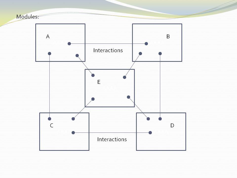
The figure shows five conventional modules (or components) and their relations (as interactions). Study almost any piece of software, and this is what you will find (even if it supposedly adheres to the so-called layering pattern).
The structure generally can be viewed as 'clumping'. Like galaxies, certain areas have higher cohesion, and so go inside boxes. Other areas are more loosely coupled, and so are represented by lines between the boxes. The difference between high cohesion and loose coupling is only quantitative.
Software health in this type of architecture is effectively management of the resulting coupling between the cohesive clumps. Allocate code to boxes in such a way as to minimize coupling. This coupling management has two conflicting forces. One is the need to have interactions to make the modules work as a system. The other is to minimize the interactions to keep the modules as loosely coupled as possible. As maintenance proceeds, the number of interactions inevitably increases, and the interfaces get wider. Cohesion will reduce, and coupling will increase over time.
Various architectural styles are aimed at managing this conflict. Most notably:
-
Layering pattern (break circular dependencies and replace them with indirections which are even worse.)
-
Try to avoid both high fan-in and high fan-out on a single module
-
Try to avoid dependencies on unstable interfaces
-
MVC type patterns
Note that none of this 'dependency management' actually avoids design-time coupling. There will always be 'implicit coupling' in both directions between modules of a decomposed system, regardless of the dependencies. This is because the modules are the opposite of abstractions - specific parts designed to interact or collaborate to make a system. For example, a function of a decomposed system will tend to be written to do what its caller requires even if there is no explicit compile-time dependency on its caller. So circular coupling may be avoided at compile-time, but will still be present at design-time. That is why in the diagram above, couplings are drawn from the insides of each of the modules in both directions. This indicates that the code inside the modules has some inherent collaboration with the code inside other modules. To the compiler or a dependency graphing tool, the lines may appear to be layered, but this is not telling you the whole story of the design-time coupling.
The compose approach
When you use abstractions instead of modules, there is qualitative difference in how the structure is built. There are no interactions, collaboration, or coupling between abstractions:
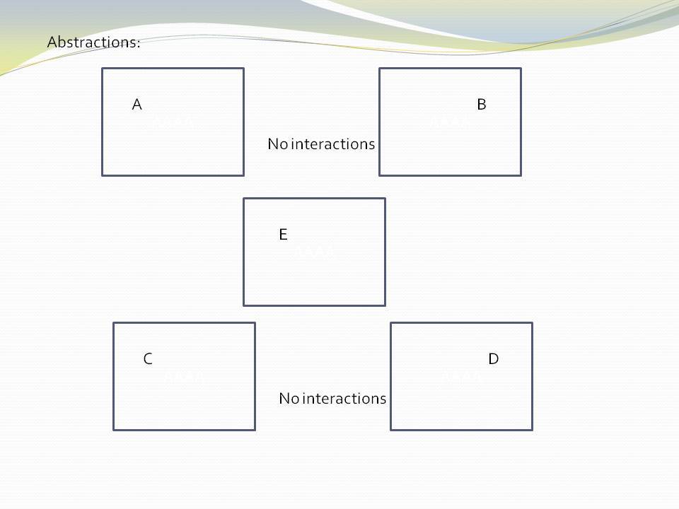
The word 'modules' has been changed to the word 'abstractions'. All the dependencies are gone. And with them all their problems. You no longer have to worry about dependencies and all their management. The implicit coupling that we talked about earlier is also gone. The 'clumping' structure has become isolated boxes. Loose coupling has become zero coupling.
The obvious question now is how can the system work? Where do all the interactions between elements that we had before go? The answer is they become normal code, completely contained inside one additional abstraction. This code composes instances of the abstractions to make a system:
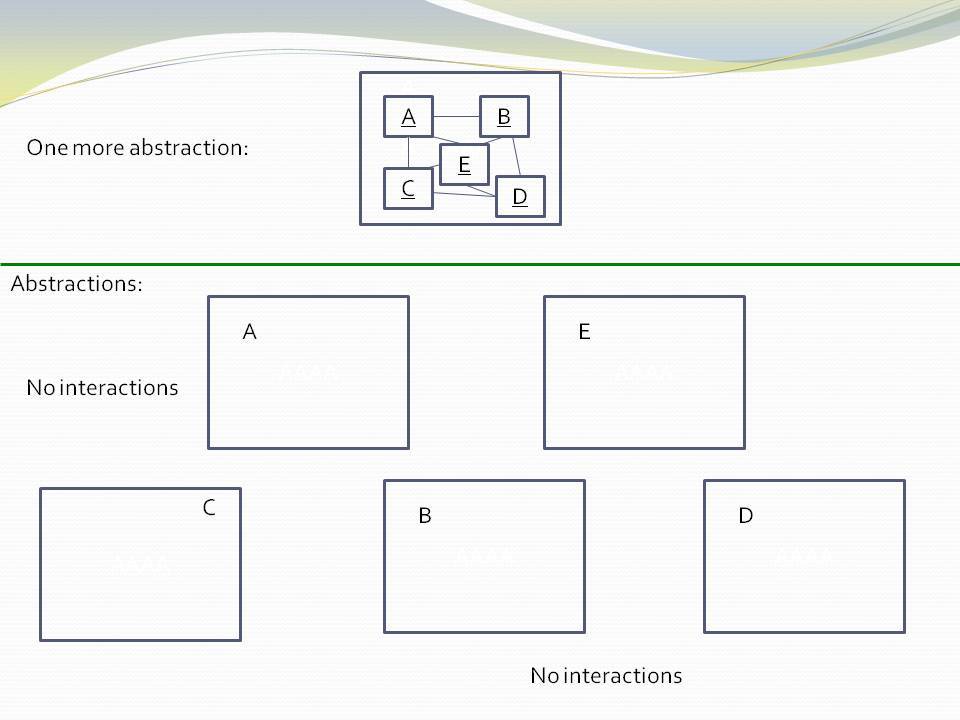
The code inside the new system abstraction does not involve dependencies between abstractions. It uses dependencies on abstractions. It’s code that instantiates abstractions and wires them together via their (even more abstract) ports. Since interactions between the instances are implemented without dependencies between the abstractions, circular wiring is fine. In fact we should embrace it, because that is how the system works.
This instantiation and wiring code is cohesive. It is the code that has knowledge of the specific system. None of the code inside the abstractions knows about the specific system, only this new code.
We put the abstractions, A, B, C, D and E into a layer. The system abstraction goes in the layer above.
|
Software engineering should not be about managing coupling. It should be about inventing abstractions. |
2.7. cf Component based development
In this perspective, we compare ALA with components, component based software engineering (component based development), components and connectors.
When you read the intentions for components, they are meant to be reusable. Since reuse and abstraction go hand in hand, it should follow that components are abstractions. Furthermore, just as we do in ALA, they have ports to supposedly allow them to have run-time communications with one another without breaking them as abstractions.
That’s the intentions. In practice, all the component diagrams I have seen fall far short of this ideal. The components themselves appear to be specific pieces of a specific system. Although they have ports to allow reuse, they are too specific to the system they are designed for to be reusable abstractions. There maybe exceptions of course, but components lack a fundamental rule that constrains components to be more abstract than the systems they are used in.
The UML component diagram uses lollipops to represent the ports. At first this seems great because it looks like you should then be able to wire them up in arbitrary ways. But, at the port level, all the example component diagrams I have seen use interfaces that are specific to one or other of the connected components. In other words the components have a fixed arrangement with each other. This in turn encourages them to collaborate and have implicit coupling with each other. It is the jigsaw analogy.
In ALA, you must have compositonality. This means the abstractions have no fixed arrangement. You have the capability to compose instances of abstractions in an infinite variety of ways. It is the lego analogy.
Component architecture does have one thing - the ability to sunstitute one component for another with the same interfaces.
Components allow hierarchical composition by having sub-components, but I am not clear on what that means. Does it mean component instances or component types? Some implementations I have seen allow you to configure the visibility of a component type. This means that component type can be completely contained inside another component type. This type of hierarchy is illegal in ALA because used components must be more abstract and therefore must be defined outside where they are public for reuse. Of course using instances of a component inside another component is the whole point of how we build up a system in either ALA or component driven development.
2.7.1. Components and connectors
One implementation model for components is so called components and connectors. The mechanics of components and connectors is that the lines drawn between components are connector objects. They contain a value, which is the 'data on the wire'. Thinking of the wire as being a variable with a value is quite a useful programming paradigm. It is also a relatively efficient execution model. The variable itself is a shared variable that isn’t globally visible. Only the two instances of components that are wired together can ever see it. Senders need only set the value of the variable, and receivers need only read the variable.
When two compatible instances of components are composed or wired together using this programming paradigm, the implied connector object is created automatically and wired inbetween them.
The instances of the components must be active objects (somehow execute by themselves).
Let’s see how to create such a programming paradigm for ALA applications:
namespace ProgrammingParadigms
{
    class Connector<T> : IOutput<T>, IInput<T> (1)
    {
        T data { get; set; } = default(T);
        T IOutput<T>.data { get => data; set => data = value; }
        T IInput<T>.data { get => data; }
    }


    public interface IOutput<T> (2)
    {
        T data { get; set; }
    }

    public interface IInput<T> (3)
    {
        T data { get; }
    }


    public static class StaticMethods
    {
        public static void Wire<T>(ref IOutput<T> Aport, ref IInput<T> Bport) (4)
        {
            Connector<T> connector = new Connector<T>();
            Aport = connector;
            Bport = connector;
        }
    }
}| 1 | The connector type itself. Instances are to be wired between two instances of domain abstractions. |
| 2 | One domain abstraction must have a port implemented as a field of the IOutput interface. |
| 3 | One domain abstraction must have a port implemented as a field of the IInput interface. |
| 4 | A method for wiring two instances of domain abstractions creates the connector for you, and then wires the two instances to it. |
Let’s create two domain abstractions to demonstrate the use of this programming paradigm. First a domain abstraction with an output port using this programming paradigm.
using ProgrammingParadigms;

namespace DomainAbstractions
{
    /// <summary>
    /// ALA Domain Abstraction
    /// Demo class to send data via a connector
    /// </summary>
    class NaturaNumbersTenPerSecond
    {
        public IOutput<int> output; (1)


        public void Run() (3)
        {
            RunAsyncCatch();
        }


        public async Task RunAsyncCatch()
        {
            // because we are the outermost async method, if we let exceptions go,
            // they will be lost
            try
            {
                await RunAsync();
            }
            catch (Exception ex)
            {
                Console.WriteLine(ex.ToString());
            }
        }


        public async Task RunAsync()
        {
            int data = 0;
            while (true)
            {
                data++;
                output.data = data; (2)
                await Task.Delay(100);
            }
        }
    }
}
| 1 | The output port |
| 2 | Outputting data to the output port |
| 3 | This domain abstraction is active, so we need a Run method to start it running. |
And another domain abstraction with an input port using this programming paradigm.
using ProgrammingParadigms;

namespace DomainAbstractions
{
    /// <summary>
    /// ALA Domain Abstraction
    /// Demo class to send data via a connector
    /// </summary>
    class ConsoleOutputEverySecond
    {
        public IInput<int> input; (1)


        public void Run()
        {
            RunAsyncCatch();
        }


        public async Task RunAsyncCatch()
        {
            // because we are the outermost async method, if we let exceptions go,
            // they will be lost
            try
            {
                await RunAsync();
            }
            catch (Exception ex)
            {
                Console.WriteLine(ex.ToString());
            }
        }


        public async Task RunAsync()
        {
            while (true)
            {
                Console.WriteLine(input.data); (2)
                await Task.Delay(1000);
            }
        }
    }
}
| 1 | The input port |
| 2 | Inputting data from the input port |
And finally an application to wire together instances of these domain abstractions:
Application.cs
using DomainAbstractions;
using static ProgrammingParadigms.StaticMethods;

namespace Application
{
    class Application
    {
        /// <summary>
        /// Application to demonstrate two active components running at different rates
        /// communicating using a connector.
        /// </summary>
        public static void Main()
        {
            NaturaNumbersTenPerSecond numbers = new NaturaNumbersTenPerSecond();
            ConsoleOutputEverySecond console = new ConsoleOutputEverySecond();
            Wire(ref numbers.output, ref console.input);

            numbers.Run();
            console.Run();
            Console.ReadKey();
        }
    }

}
2.8. Real world analogies
2.8.1. Atoms and molecules
Here are two atom abstractions:


Instances can be composed to make a molecule:

If water was implemented in the same way we typically write software, there would be no water molecule per se; the oxygen atom would be modified to instantiate hydrogen atoms and interact with them. Even if dependency injection is used to avoid the instantiating, it is still unlikely that a water abstraction would be invented to do that, and there would still be the problem of the oxygen atom interacting with hydrogen’s specific interface. The oxygen module still ends up with some implicit knowledge of hydrogen. And hydrogen probably ends up with some implicit knowledge of oxygen in providing what it needs.
This implicit knowledge is represented by the following diagram. The relationship is shown coming from the inner parts of the modules to represent implicit knowledge of each other.
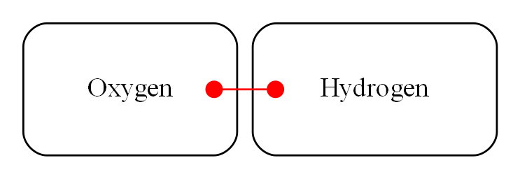
While oxygen and hydrogen are modules, they are not abstractions because oxygen is implicitly tied to hydrogen and vice-versa. They can’t be used as building blocks for any other molecules.
To keep oxygen as abstract as it is in the real world, an interface must be conceived that is even more abstract than oxygen or hydrogen. In the molecule world this is called a polar bond. It is one of the programming paradigms of molecules. Its execution model at run-time is the sharing of an electron.
The corresponding software would look like this:
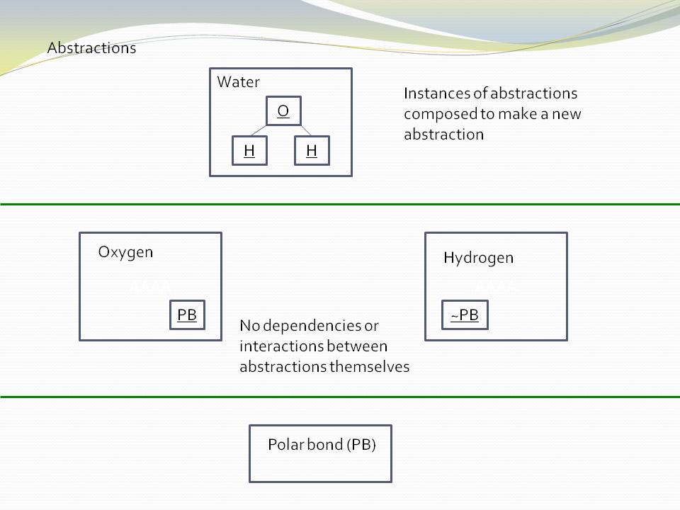
The water molecule has a "uses instances of" relationship with the two atoms, and the atoms have a "uses instance of" relationship with the even more abstract polar bond abstraction. Polar bond is an example of an 'abstract interface'.
2.8.2. Lego
The second real world analogy is Lego. Shown in the image below is the same three layers we had above for molecules, atoms and bonds.
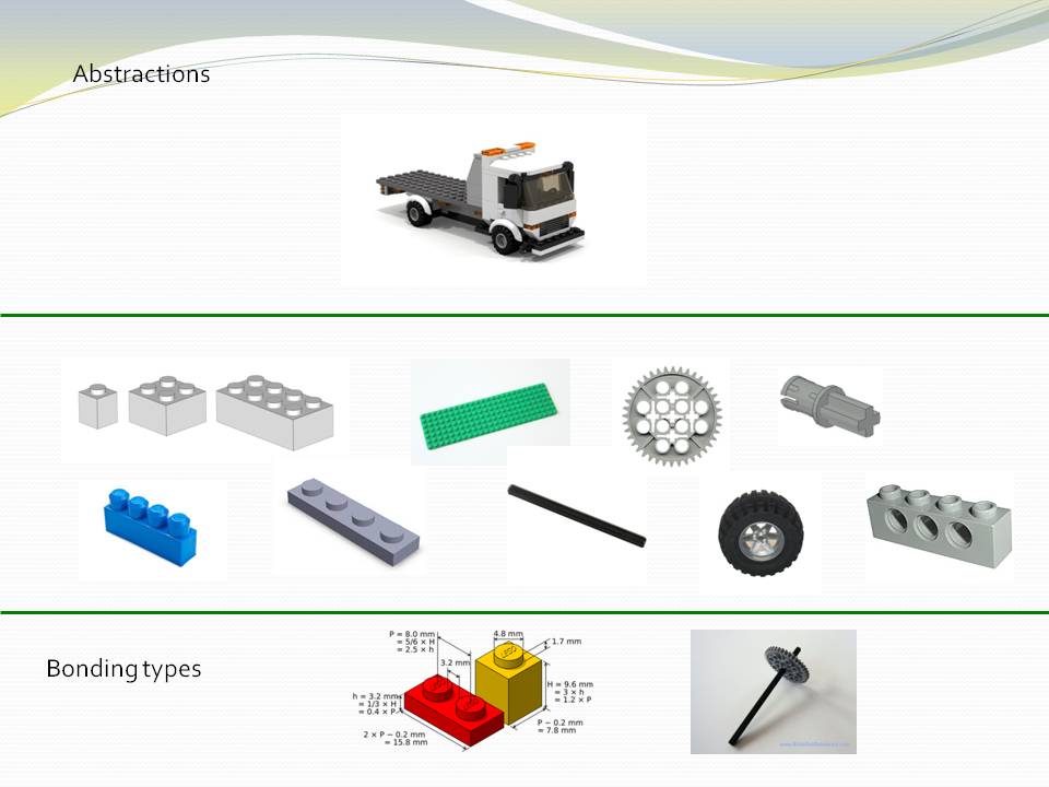
The domain abstractions are the various Lego pieces, instances of which can be assembled together to make specific creations. Lego pieces themselves have instances of an abstract interface, which is the stud and tube. This is a programming paradigm. There is a second abstract interface, the axle and hole. These programming paradigms have an 'execution model' at run-time. The execution of the stud and tube programming paradigm is to hold structural integrity. The execution of the axle and hole programming paradigm is rotation.
Conventional code analogy
If Lego is a good analogy for ALA, then what would be a good analogy for conventional code?
It’s an upside down jigsaw puzzle.

The pieces are modules, and the interlocking shapes are the interfaces. The picture is the application or system.
Like the interlocking shapes, interfaces tend to be specific to pairs of modules. They may nominally belong to one module or the other, but the complimentary one bends to that interface, and vice versa. They have one rigid structure for how they fit together. The fixed relationship between modules tends to cause collaboration and coupling between them, and this tends to get worse over time as new features or user stories are added.
The jigsaw puzzle is upside down because there is no view of the complete picture. You are allowed to pick up one piece at a time and look at the part of the picture that’s on the other side. This is the equivalent of opening one module and reading the code inside it. By doing this repeatedly for many adjacent modules, you can start to get an idea of how part of the bigger system works. But, you have to keep the pieces of picture in your head, because there is no explicit view of it.
A jigsaw is all in one layer. The big picture, interfaces and pieces all exist in that one layer as a single information entity. ALA has at least three layers of information. Firstly, the general ways that pieces can be combined is an information entity in the lower layer. The building block types exist the next higher layyer. And particular arrangment of instances of building blocks is a separate information entity in a higher layer.
Essentially ALA, like Lego, has the property of compositionality. Conventional code modules, like jigsaw pieces, generally do not.
2.8.3. Electronic schematic
The third real world analogy comes from electronics. The abstractions are electronic parts, instances of which can be composed as a schematic diagram:
In this domain, we have at least two abstract interfaces as programming paradigms, one for digital logic signals and one for analog signals. Their execution model at run-time is continuous-time voltage levels.
2.8.4. A clock
Our forth and final real world analogy is a clock. In this diagram, we show the process of composition of abstractions to make a new abstraction. The process is a circle because instances of the new abstraction can themselves be used to make still more specific abstractions. Each time around the circle adds one layer to the abstraction layering.

Let’s go round the circle once. We start with abstract parts such as cog wheels and hands. Instances of these have abstract interfaces as programming paradigms. Their execution models allow them to interact at run-time, such as spinning on axles and meshing teeth. The next step is to instantiate some of these abstractions and configure them. For example, configure the size and number of teeth of the cog wheels. Next comes the composition step, where they are assembled. Finally we have a new abstraction, the clock. Instances of clocks can in turn be used to compose other things such as scheduling things during your day. Because you have now created the abstraction clock you don’t have to think about cog wheels when thinking about how to meet someone at a certain time.
There are many other instances of this pattern in the real world, and in nature. In fact everything appears to be actually composed in this way. At least that’s the way we understand and make sense of the world - in terms of abstractions, which are in composition layers.
2.9. Example Project - Coffee machine
Robert Martin posed an interesting pedagogical sized embedded system problem about a coffee maker in his book “Agile Software Development: Principles, Patterns and Practices”. The original chapter can be found by searching for “Heuristics and Coffee”.
Although I agreed with Martin that his students' 'object oriented' solutions were hideous, I did not like his worked solution either. Although he had claimed to use abstractions, they were actually collaborating modules, just with abstract sounding names. So you had to read all the code to understand any of it. I wanted to know if ALA would tame the problem into a solution as succinct as the requirements. Because this is the first ever ALA project I did, some of the more refined ALA conventions, patterns and methods are not used here. But the fundamental constrains are met, and the result is spectacularly simple compared to Martin’s solution.
Martin’s worked solution to this problem uses decomposition into three modules that collaborate or interact with one another. The ALA solution follows the opposite philosophy. It has three abstractions. They come from the specification - a button with an indicator light, a warmer plate, and a boiler. They do not collaborate or interact with one another. As domain abstractions, they also know nothing about the coffee machine. The coffee machine is then constructed (as another abstraction in the top layer) that makes use of the three domain abstractions.
This example uses different execution models from the UI and dataflow ones that we use a lot in other examples. Here we use some simple, yet quite interesting electronic-signal-like execution models that use a simple main-loop polling type implementation, just as Robert Martin’s original solution also had.
Reading an ALA application requires first knowing the pre-requisite knowledge you need from lower layer abstractions. So before presenting the application, let’s first familiarise ourselves with the abstractions we need from the domain layer, and the Programming Paradigms layer.
2.9.1. Domain abstractions layer
Here are the three domain abstractions:
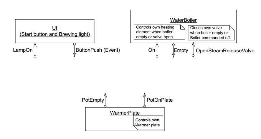
Take a moment to look at these three abstractions:
— The UI has a lamp you can control, and a push button which outputs an event (should have been two separate abstractions).
— There is a WarmerPlate. It tells you whether or not a container is on the warmer plate, and whether or not it is empty. It controls its own heater.
— There is a Boiler. It can be turned on or off. It will tell you when it is empty of water. And you can stop water flow instantly with a steam release valve. It will turn its own heater off if it runs out of water, or the valve is opened.
That’s all there is to know about the three domain abstractions.
2.9.2. Programming Paradigms layer
We have three programming paradigms
— live dataflow (works like an electronic circuit)
— events
— simple state machine
The API for the Programming Paradigms layer is described in the key on the right of the diagram below. It gives you all the knowledge from this layer to be able to read the diagram. So, for example, a solid line is a dataflow; the rounded box is state with the states enumerated inside it.
The details of how to turn the diagram into code is explained in a project document, also provided in the Programming Paradigms layer.
2.9.3. Application layer
Now that we have understood the knowledge dependencies in all lower layers, we can read the diagram that resides in the top layer, the application layer:
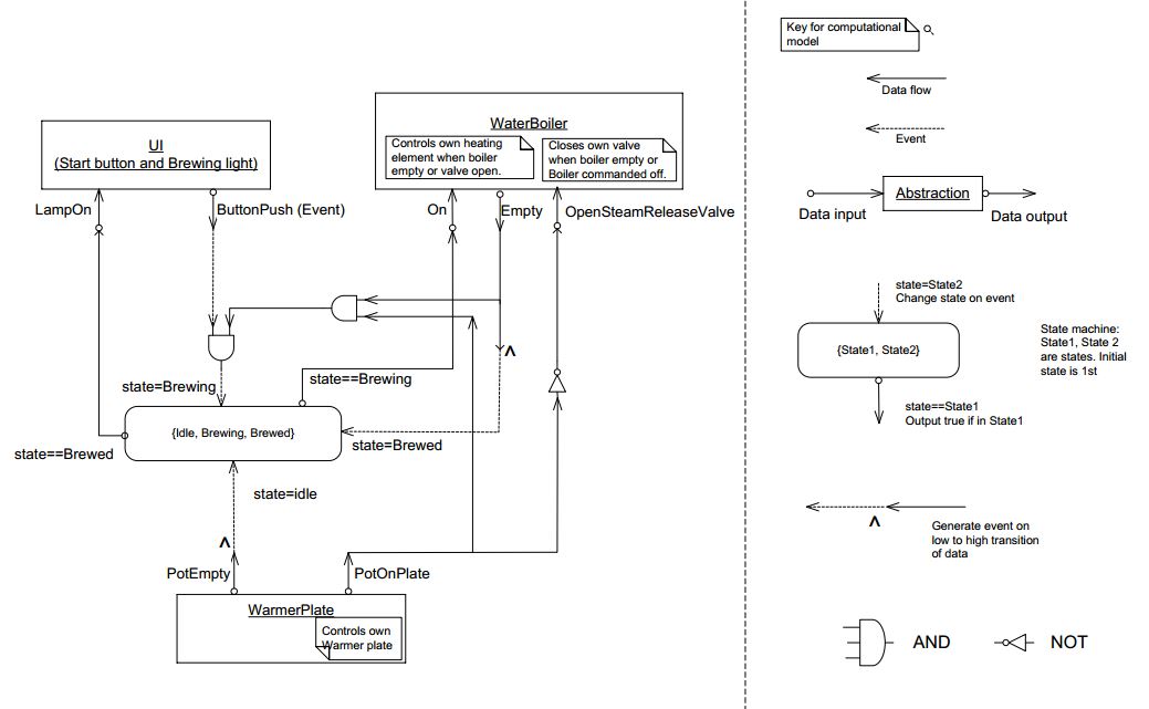
The diagram to the left is the application itself. Instances of the three domain abstractions, UI, Boiler and Warmer plate are shown as boxes.
Follow me now as we go through the user stories by looking at the lines on the diagram:
-
When the UI push button is pressed, we set the state to Brewing, provided the Boiler is not empty and the pot is on the Warmerplate. (On the diagram, it looks like a NOT operator is missing on the Empty signal from the boiler to the AND gate.)
-
When the state is brewing, it turns on the boiler, and coffee making starts.
-
If someone takes the pot off, the valve is opened to momentarily release pressure from the boiling water, which stops the water flow.
-
When the boiler becomes empty, the state is set to Brewed. When the state is Brewed, the light in the UI is on.
-
When the coffee pot is replaced empty, the state goes back to the idle state where we began.
That’s all there is to reading this application. The code for the coffee machine can be read and understood in about one minute. Compare that with reading other solutions to the coffee machine problem.
Note that the paragraph above is pretty much a restatement of the requirements in English. It could have been the requirements. The amount of information in the English form (or the diagram form) is about the same, thus the Domain Abstractions gave us the correct level of expressiveness. Further confirmation of this is if the level of expressiveness allows us to modify it.
For example, say a requirement was added that a coin device was to enable the machine to be used. The coin device is an abstraction that provides an output when a coin is given, and has a reset input. Looking at the diagram, and being able to reason about its operation so easily, you can see that the coin device’s output would intercept the Pushbutton using another instance of an AND gate. And to reset the coin device, you could use the boiler empty output event.
2.9.4. Execution
To make it actually execute, we apply the manual procedure documented in “Execution models.doc”. This document is in the Programming Paradigms layer. It will generate these 6 lines of code:
if (userInterface.Button && warmerPlate.PotOnPlate && !boiler.Empty) { state = Brewing; } userInterface.Button = false;
boiler.OpenSteamReleaseValve = !warmerPlate.PotOnPlate;
boiler.On = state==Brewing;
if (boiler.Empty && !prevBoilerEmpty) { state = Brewed; } prevBoilerEmpty = boiler.Empty;
if (warmerPlate.PotEmpty && !prevPotEmpty) { state = Idle; } prevPotEmpty = warmerPlate.PotEmpty;
userInterface.LightOn = state==Brewed;
There is a one-to-one correspondence between the lines in the diagram and the lines in the code.
As you can see, the execution model is a simple one. The 6 lines of code are continually executed in a loop. This execution model is effective and appropriate for this small application.
The 6 lines of code can be built into a complete program shown below:
 #ifndef _COFFEE_MAKER_H_
 #define _COFFEE_MAKER_H_
 // Coffee Maker domain abstraction
 #include "CoffeeMakerAPI.h"  // original hardware abstraction supplied by hardware engineers
 // Knowledge dependencies :
 // "PolledDataFlowProgrammingParadigm.doc" -- explains how to hand compile a dataflow diagram of this type to C code
 // Following are 3 Domain abstractions that the application has knowledge dependencies on


 #include "UserInterface.h"
 #include "Boiler.h"
 #include "WarmerPlate.h"


 class CoffeeMaker
 {
 private:
    enum {Idle, Brewing, Brewed} state;
    Boiler boiler;
    UserInterface userInterface;
    WarmerPlate warmerPlate;
    bool prevBoilerEmpty, prevPotEmpty;
    void _Poll();
 public:
    CoffeeMaker()
        : state(Idle), prevBoilerEmpty(boiler.Empty), prevPotEmpty(warmerPlate.PotEmpty)
    {}
    void Poll();
 };
 #endif //_COFFEE_MAKER_H_
 // CoffeeMaker.c
 // This is not source code, it is code hand compiled from the CoffeeMaker application diagram
 #include "CoffeeMaker.h"

 void CoffeeMaker::_Poll() (1)
 {
    if (userInterface.Button && warmerPlate.PotOnPlate && !boiler.Empty) { state = Brewing; } userInterface.Button = false;
    boiler.OpenSteamReleaseValve = !warmerPlate.PotOnPlate;
    boiler.On = state==Brewing;
    if (boiler.Empty && !prevBoilerEmpty) { state = Brewed; } prevBoilerEmpty = boiler.Empty;
    if (warmerPlate.PotEmpty && !prevPotEmpty) { state = Idle; } prevPotEmpty = warmerPlate.PotEmpty;
    userInterface.LightOn = state==Brewed;
 }


 void CoffeeMaker::Poll()
 {
    // get inputs processed
    userInterface.Poll();
    boiler.Poll();
    warmerPlate.Poll();
    // run application
    _Poll();
    // get outputs processed
    userInterface.Poll();
    boiler.Poll();
 }
| 1 | The 6 lines of code appear in the "CoffeeMaker::_Poll()" function. |
If you are using a diagram as we are in this solution, you always change the diagram first when the requirements change. It provides the expressiveness needed to see the application’s requirements represented in a clear, concise and cohesive way. There the logic can be ‘reasoned’ with. It is not documentation, it is the source code representation of the requirements, and executable, both important aspects of ALA.
The next step is to implement the three abstractions. These are straightforward using the same execution model as was used for the application, so are not shown here.
The resulting application passes all of Martin’s original acceptance tests plus a number of additional tests of behaviour gleaned from his original text.
3. Chapter three - Why the structure works
In the previous chapter we described what the structure, the anatomy, of ALA looks like as if we were dissecting a dead body. We saw where things are located but we didn’t get an understand of why they are there. In this chapter we explain why that structure works. Why does this way of organising code result in software that meets those non-functional requirements we listed in Chapter one?
The organisation of this chapter (and all chapters) is to use different perspectives. We all have different prior knowledge on which we build new knowledge, so we will each have a different best way to understand things. Use the perspective that makes the most sense to you. Because of the use of perspectives, there will be some repetition of ideas between the major sections in this chapter.
3.1. A thought experiment
For this first perspective, imagine you are reading the following function, abc123, and trying to understand it:
float abc123(float[])
{
    ...
    b = xyz789(a)
    ...
}
float xyz789(float)
{
    ....
    // complicated code
    ....
}
You see that the function abc123 uses function xyz789. So you follow the indirection, an inconvenience at the least because you are really just wanting to understand abc123. Following the indirection may involve an all files search to even find xyz789. Then it’s also not clear what xyz789 does. You have to mentally stack where you were in the code at abc123, including everything you understand about it so far, and start concentrating on xyz789.
Despite only having about 20 lines of code, xyz789 is complicated. You need to use the code in abc123 to try to unravel what xyz789 might be providing for it. A comment mentions that it uses a CORDIC algorithm and gives a reference. But before following that indirection as well, you note that both abc123 and xyz789 have the following properties:
-
they are modules
-
apparently loosely coupled
-
have a simple interface
-
use encapsulation of internals
-
use no external variables
-
have no side effects
-
hide information
-
probably separate two concerns
-
are small
-
follow coding guidelines
-
have comments
Despite having all these great properties that we are taught our code should have, we are still forced to read both functions to understand the code in either of them. They are effectively fully coupled at design-time - understanding any of the code involves understanding all of the code.
Now we make one small change:
float StandardDeviation(float[])
{
    ...
    b = Sqrt(a)
    ...
}
float Sqrt(float)
{
    // complicated code
}
Suddenly understandability is absolutely transformed. All we did was make the two functions abstractions. Now we don’t have to read the complicated code inside xyz123 at all. We don’t have to follow the indirection. The code inside each of the two functions goes from highly mutually coupled to zero coupled.
All those other attributes that we listed above seemingly made no difference. The quality attribute that really mattered was abstraction. The others are still good to have, but they are completely insufficient. The abstraction property is the one that our brains have evolved to use.
The quality of abstraction is somewhat subjective. We don’t really have a good way to measure it. No compiler or tool can yet check that quality. However, a software engineer’s job is inventing good quality abstractions.
-
In the downward direction, design-time coupling goes to zero because the standard deviation function need only know about the concept of the square root abstraction, not about any of the code that implements it.
-
In the upward direction, coupling goes to zero because we don’t need to know about the caller to try to tease out what we are providing. By being an abstraction, square root is reusable, and can’t know anything about the more specific Standard deviation abstraction that happens to use it.
There are other benefits too:
-
Abstraction and stability go hand in hand. The Sqrt abstraction is as stable as the concept of squareroot. That’s a concept that’s been stable for thousands of years. The Standard Deviation function has a dependency on something that has been stable for thousands of years! All dependencies in an ALA program go in the direction of the more stable.
-
Abstraction and reuse go hand in hand (as pointed out by Krueger). The more abstract an abstraction is the more reusable. Code reuse in ALA programs increases markedly.
-
The complicated code inside SQRT no longer matters at design-time. It is completely isolated by the abstraction. If your brain already knows the SQRT concept (I had to choose one that everyone knows), there is no need to follow the indirection when reading the code inside StandardDeviation. The reader just continues reading the next line of code after the Sqrt invocation as if Sqrt is just like any other line of code in their base language. That’s what abstraction does, and only abstraction can do this. If you don’t already know what a given abstraction is from it’s name, then you need to follow the indirection once and read a comment that should describe each abstraction written just ahead of each abstraction.
With this new understanding, we will now define the word dependency to be compile-time relationships, and coupling to be the design-time. One is what the compiler sees, the other is what our brain sees.
Using these definitions, you can have coupling without dependencies (sometimes called implicit coupling). The reverse is also true - it is possible to have dependencies without coupling. ALA makes use of this by simply making a constraint that all dependencies must be on abstractions. When you do that, every artefact (abstraction) in the program is zero-coupled with every other.
Doing this isn’t always easy because unfortunately there are many established architectural methods, patterns and styles that break this constraint. On the other hand, applying this constraint emerges some patterns that we will immediately recognise. DSLs and dependency injection are two examples. We will also emerge some less well known ones that are none-the-less not novel. There already exists an "abstract interactions" pattern, for example, which uses interfaces that are more abstract than the modules using it.
There are two situations that commonly cause coupling in conventional code:
-
In the above example, imagine that xyz789 isn’t an abstraction that is more abstract than abc123. Lets pretend for a moment that its just a source or destination for messages (in the same abstraction layer as abc123) such as a display. Then abc123 cannot be an abstraction because it cannot be reused without dragging xyz789 with it. If abc123 is an abstraction, it cannot know (or care) where the data comes from or goes to. To fix this, xyz789 must be passed into abc123 by something else above both of them. In other words, they must be composed. This can be passing in a function, passing in an object (dependency injection), or other mechanism such as function composition, monad composition, or the WireTo operator that we will use a lot in our ALA example projects.
In conventional code, if abc123 calls directly xyz789, then the connection relationship between abc123 and xyz789 is hidden inside abc123. In ALA that relationship has to be an explicit line of code (inside another abstraction) in the layer above that composes the two instances. There, it will be cohesive with other similar relationships that work together in a collaborative way to make the application.
Often these collected together wirings form a graph, making diagrams rather than code an even better way to describe the application.
-
In conventional code, if xyz789 provides a part of the implementation of abc123, it will be more specific than abc123. Sometimes such a function or class is called a helper or submodule because xyz789 could only ever be used by abc123. In ALA xyz789 needs to be significantly more abstract than abc123 or it will be highly coupled to it. If xyz789 is put inside abc123 the complexity inside abc123 is still that of both of abc123 and xyz789 together.
This is contrary to what we are taught. We are taught to "divide and conquer" or to separate out the responsibilities. If we do this arbitrarily, we will end up with specific pieces (such as UI and business logic) which are highly coupled with each other, and with the specific application. We need to work hard to separate only by finding abstractions - potentially reusable artefacts. Then we configure instances of those abstractions for each specific use by passing the application specific details into them.
In summary, ALA’s starting premise is a constraint. The constraint is that you can only use one type of dependency - a dependency on an abstraction that is significantly more abstract than the one using it. This is not only quite feasible, but results in zero coupling throughout the entire program.
3.2. Abstractions
In this perspective, we look at what abstraction really are. This is itself the most abstract perspective we will take in this chapter.
3.2.1. Design-time encapsulation
|
Abstractions are the human brain’s version of encapsulation. |
The maintainability quality attribute is often thought of in terms of ripple effects of change. I don’t think that is quite the right way to look at it. I have often had to make changes across a number of modules in poorly written code. The changes themselves just don’t take that long. The problem I see is the time you have to spend understanding enough of the system to know where to make a change, even if it ends up being just one line of code in one place. To make that small change with confidence that it wont break anything can take a long time understanding the collaboration between modules. You may have had to understand a lot of code to figure that out. You have to understand all the code that is potentially coupled to that one line of code, which is essentially the complexity.
Unlike encapsulation which works at compile-time, abstractions hide complexity at design-time. They give boundaries to how far you have to read code to understand it.
3.2.2. Abstractions and Instances
|
Software architecture should contain two concepts for its elements equivalent to abstractions and instances. |
If you are going to have abstraction, it makes sense that you would have instances. An instance is nothing more than the use of an abstraction by referring to its name. If your abstraction is a pure function, then an instance is just using the function, or getting a reference to it.
If your abstraction is a class, and if that class contains data, then you need to instantiate the class so that each instance has its own data. Object oriented languages of course already have these two concepts as classes and objects.
Many discussions on software architecture seem to combine them into one term, such as modules or components. These terms may implicitly contain the separate concepts of abstractions and instances, or they may be intended to have only one instance, in which case it can’t be an abstraction. Not having explicit terms, like class and object, will inevitably lead to confusion. In ALA the terms we use are abstractions and instances.
The problem is that when we become vague about the difference between abstractions and instance, we will then create dependencies between abstractions such as to get or put data. If you create dependencies between peer abstractions, they are no longer abstractions. Instead you need to wire the instances. If we don’t have two separate and clear terms for abstractions and instances, we will end up with no abstractions. All architectural styles based on a 'divide and conquer' methodology appear to have this problem.
A confusion comes from the UML class diagram, which already has the separate concepts of classes and objects. However it actually encourages you to create relationships between classes, destroying them as abstractions. The most important potential idea that OOP brought us was the idea of classes as reusable abstractions, and objects as their instances. It never happened in part because of the UML class diagram, and the very harmful habit of putting dependencies between abstractions instead of wiring instances.
3.2.3. Abstractions enable composability
An important property of abstractions is that instances of abstractions can be composed or assembled in an infinite variety of ways. We call this composability. We discuss composabilty in detail in a section below.
Even the tiniest amount of coupling between two abstractions completely kills composability, meaning they are no longer abstractions. So one test of abstractions is composability of their instances. If any two potential abstractions must work together, then they are not abstractions, they are just modules.
3.3. Zero coupling and higher cohesion
In this perspective, we look at ALA in terms of coupling.
3.3.1. Zero coupling
ALA has mutual zero coupling between the code inside (the code that implements) all abstractions. This is the case both horizontally between peers in the same layer, and vertically up or down the layers.
In software development we are only interested in design-time coupling. This means that to understand one piece of code, how much do we need to know about other pieces of code? It is about knowledge, which is about design-time. This is the coupling that matters.
We will use the word coupling to mean design-time coupling. That’s consistent with Larry Constantine’s statement. His reasoning came from identifying how to reduce complexity, the time taken to understand software, and reducing the incidence of bugs.
Here is a typical definition of Loose coupling from the internet: "Loose coupling refers to minimal dependencies between modules, accomplished through strict, narrow, stable interfaces at the boundaries."
This definition of coupling differs from ALA’s in two respects.
Firstly, we are not minimizing dependencies. We are eliminating bad dependencies and maximizing good dependencies (as discussed later).
Secondly, it’s not just about using interfaces. A lot of design-time coupling is what I call collaboration coupling. Collaboration coupling is when one module does specifically what another module needs. Collaboration between two modules is often mutual. It’s characterised by the modules having a fixed arrangement with each other (for example, an MVC type of arrangement). (To understand what we mean by "a fixed arrangement", see the section below on the opposite of a fixed arrangement, which is composability.)
An interface between two modules that have a fixed arrangement with each other may hide some details, but it doesn’t prevent fundamental collaboration between the two modules. When modules have a fixed arrangement with each other, collaboration will tend to increase during maintenance.
Some definitions of coupling are in terms of the ripple effects of change. But even if a change ends up being made in just one place, that doesn’t mean you didn’t have to understand code in multiple places before you could understand how to make the change. I have many time spent a day understanding code only to end up changing one line. So this is not a good definition.
Wikipedia defines coupling as "the degree of interdependence between software modules". It doesn’t really distinguish between design-time, compile-time or run-time coupling, and the given formula for coupling seems to reflect compile-time. We need to think of coupling as a design-time property. It is about knowledge of internals of a module. Compile-time and run-time dependencies do not matter. Only design-time coupling matters.
Abstractions are the only type of modules that allow us to achieve zero coupling.
Unfortunately there is a meme in the software engineering industry that there must be some coupling between modules. The argument goes that if the system is to do anything it must have some coupling between its parts. We therefore hear of "loose coupling" as being the ideal. Using the definition of coupling given above, this is completely incorrect. It’s confusing run-time coupling with design-time coupling. Only design-time coupling does. If I connect an instance of difference table generator to an instance of a printer, that run-time coupling between the instances doesn’t create any coupling between the concept of a difference engine and the concept of a printer. I can still understand either concept’s implementation in complete isolation, even though it’s possible to connect instances of them together to form a working system.
Because of this bad meme, in conventional code we have developed a habit of using dependencies to implement communications. We are settling for design-time coupling to implement run-time communications between different parts of a system. It is not necessary. Part of the problem is that we are seldom taught the difference between design-time and run-time coupling. So I prefer to use the words connection or wiring used for communications between instances of parts in a system.
For example, in conventional code, if function Switch calls function Light, the code inside Switch is coupled with Light. If the light’s abstraction level is about the same as that of the Switch (which it is), then the abstraction of Switch is destroyed. When you reuse it you have to know the internal code brings in a Light as well. To understand the system (a Switch connected to a light), you have to go inside the Switch:
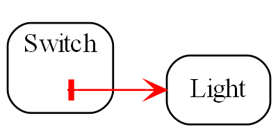
If instead, a separate abstraction called "System" has code inside it like Light(Switch()), then Switch remains a good abstraction whose internal code is now only concerned with how a switch works. The code inside all three abstractions is now zero coupled. Understanding the system no longer requires looking inside Switch:
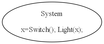
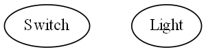
A similar argument applies if Switch and Light are classes. In conventional code they will commonly have an association relationship. Even if Light is injected into Switch by a higher entity called System, Switch still knows the specific interface of a light (LightOn(), LightOff()). This interface is not abstract enough to prevent Switch knowing about Light, and Switch knowing about the System. If you instead have a class, System, that has code like new Switch().WireTo(new Light()) using a generic interface then all three abstractions are zero coupled.
ALA never uses coupling for connections or wiring between parts of a system. A larger system typically consists of many connections. These connections are typically cohesive, and belong in one place. In conventional code they tend to be distributed and buried inside the modules. A smell is that you are doing 'all files' searches to unravel them. In ALA, they are brought out into their own place as a cohesive new abstraction describing a specific user story or system.
3.3.2. Cohesion
|
"In ALA, Collaboration becomes cohesion". |
What would be collaboration between modules in conventional code becomes cohesion inside a new abstraction in ALA. A call from one module to another becomes a single line of code inside an abstractoion in a higher layer. Would be collaboration between a group of modules for a single purpose or user story (like MVC pattern) becomes several cohesive lines of code in the higher layer. Those several lines of code are cohesive.
Cohesion also increases for the modules as they become abstractions. An abstraction is closely aligned with the single responsibility principle. We can think of abstraction as a "single concept principle" instead of "single responsibility principle". Using abstractions increases the cohesion of the code that implements the abstraction.
ALA provides no structure for the internals of an abstraction because the code is cohesive. The internals of an abstraction could be described as a small ball of mud, which is why they should be small. There is no such thing as a sub-abstraction. Instead the code is composed of instances of abstractions from lower layers. So in ALA, layers replace what would be hierarchical encapsulation in conventional code structures.
Zero coupling and higher cohesion blocks ripple effects of change, whether in higher layers or lower ones. A ripple stops at an abstraction concept because of the inherent stability of the concept itself.
What can happen though is that abstractions can be improved to be better quality abstractions. Often you can generalize an abstraction to make it more reusable by adding a configuration. The configuration has a default, so it doesn’t affect existing uses of the abstraction (convention over configuration).
In our experience, the most common type of change that still affects multiple abstractions are changes to code conventions. Conventions in the ways abstractions are commented, and their code laid out are effectively abstractions in themselves that live in a bottom layer. So when they change, it makes sense that all abstractions that depend on them change. These conventions will mature over time. Besides, while these types of changes may require a lot of editing, they don’t require simultaneous understanding of multiple modules, which is where the real problem with coupling lies.
3.4. Good versus bad dependencies
In this perspective, we look at ALA in terms of good and bad dependencies.
Often software engineering design is done from the perspective of managing dependencies.
A dependency is when some code symbolically refers to a class, interface or function or other artefact that’s in a separate piece of code. This covers everything from dependencies on classes, interfaces, modules or components, to dependencies on libraries or packages.
A dependency can be on something public inside a class or interface, usually a method or property. Even if using an object reference, there is still a dependency if there is a reference to something named inside the class or interface.
We need to distinguish between good and bad dependencies. Good dependencies are design-time dependencies. These are dependencies on concepts you must know to even understand a given piece of code. I will often refer to this type as a "knowledge dependency" or "use of an abstraction". It is also sometimes called "semantic coupling". This type of dependency effectively adds to the language you use to write code. Here is a diagram showing a good dependency.
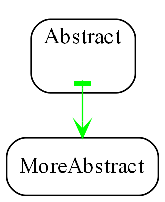
A bad dependency is one that is there to facilitate run-time communications between two modules or components. Here is a diagram representation.
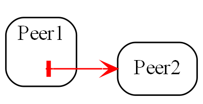
Another type of bad dependency is when a module uses a submodule that is a specific part of it:
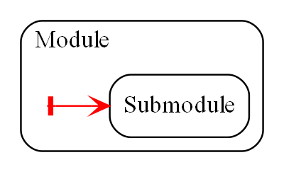
An example is a 'helper' class. The submodule is often thought of as being logically contained inside its parent module, even if it not actually encapsulated inside it, because the module is not used by anything else.
|
Dependencies on more abstract abstractions are good. |
|
Dependencies for communciations between peers are bad, as are dependencies on submodules. |
A simple example of a communication dependency is a module that calculates the average then calls a display module to display the result. To understand the code that calculates the average requires no knowledge about displays, nor even where the result will be sent. So it is a bad dependency.
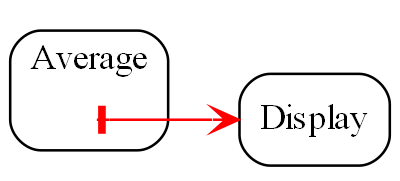
The intention of the fixed arrangment between Average and Display was to measure rainfall. To do that, an instance of an Average module needs to be connected to an instance of Display module at run-time, but you don’t need a bad dependency to achieve that. Instead you use two good dependenies:
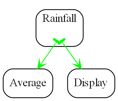
A simple example of knowledge dependencies occurs in an abstraction that meters rainfall. To understand the rainfall code, you must understand the concepts of average and of display. It’s a good thing to build the rainfall meter abstraction using the concepts of averaging and displaying.
We typically find both good and bad dependencies in conventional code. A typical modular program is full of bad dependencies. But whether a knowledge dependency or a communication dependency, they all look syntactically the same - a function call or a 'new' keyword or a method call. We are not generally taught how to distinguish between them. We lump them together when we talk about dependency management, loose coupling, layering, fan-in, fan-out, circular dependencies or dependency inversion. Dependency graphing tools do not distinguish between them because identifying good dependencies would require understanding the levels of abstraction.
Good and bad dependencies are not just good and bad. They are really good and really bad.
A knowledge dependency is good because it’s only a dependency on an abstract concept, something stable and learnable. Once learned we never have to follow the indirection to understand the code that uses the abstraction. We want more of them, because then we are reusing our abstractions, and that just means they are better abstractions. The more dependencies you have on an abstraction, the more abstract it is.
Bad dependencies destroy abstractions. They cause explicit and implicit coupling. They obscure the structure of the application by distributing that structure implicitly throughout its modules.
So it’s doubly important that we are able to tell good dependencies from bad.
|
ALA is simply the elimination of ALL bad dependencies. |
It’s entirely possible to build a system using only good dependencies.
When we remove bad dependencies, each one is transformed into a normal line of code. That line is inside a more specific abstraction in a higher layer. The line uses two good dependencies that refer to the two abstractions in the layer below, wiring them together by their ports. These lines of code are cohesive with one another instead of being spread throughout the modules, creating a new abstraction that represents the composition.
Consider the diagram below representing the conventional modular way to write a rainfall meter. An ADC reading is averaged, converted, accumulated, and displayed. The middle three modules have bad dependencies, which they use to make function calls to pull data in and push data out.
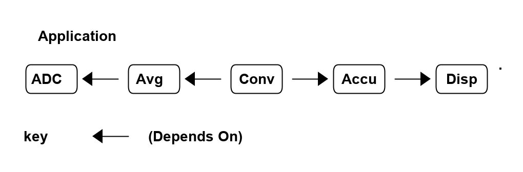
There are four bad dependencies, two from Conv and one each from Avg and Accu.
Now consider this diagram, where we have transformed it to use only good dependencies.
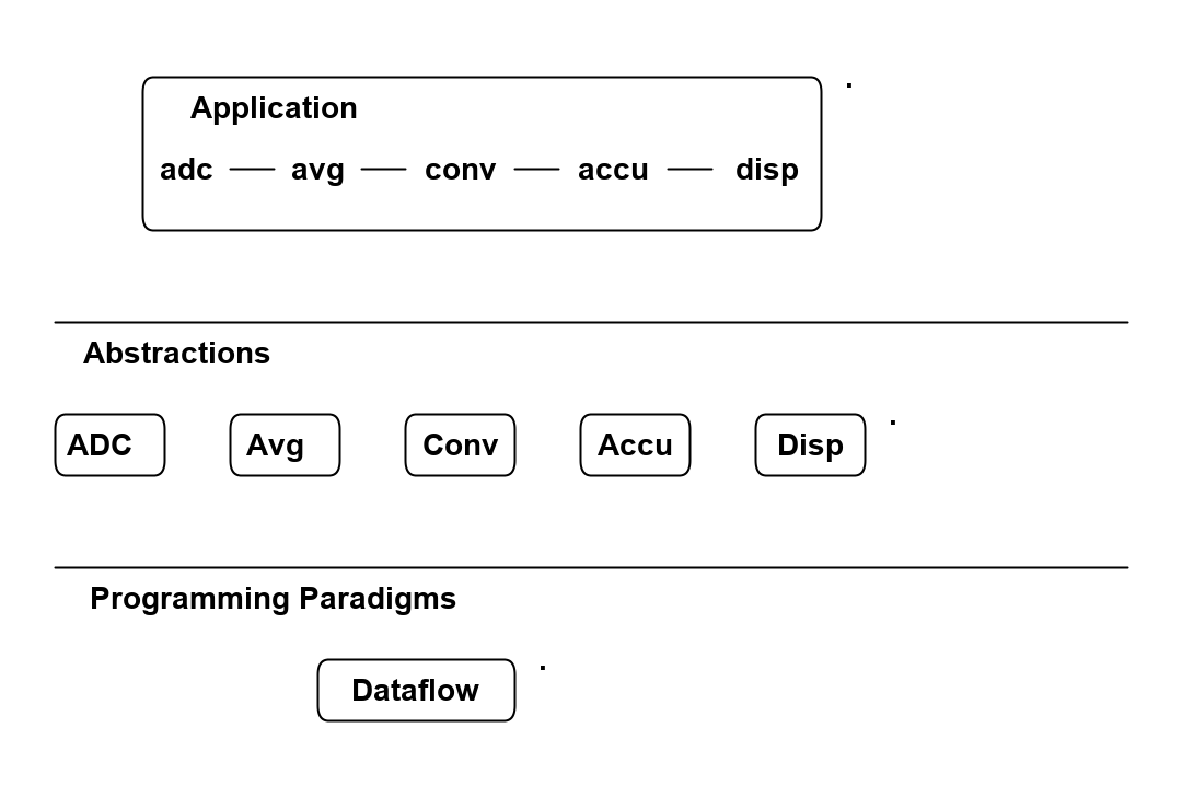
The lines in this diagram represent wirings not dependencies. The wiring represent dataflow, a very abstract compositional concept.
The lower-case letters used in the top layer of the diagram represent instances of the respective abstractions. (In UML they would be underlined.)
Note that, we could have used arrows instead of lines between the instances, but the direction would not represent the direction of dependencies but the direction of the dataflow.
There are five good dependencies from the Application to the five Abstractions. These are represented by the lower case names using the abstractions with the corresponding uppercase letters.
There is also a good dependency on the dataflow abstraction used for the wiring.
Connections between the instances of the abstractions are completely described inside the Application abstraction. There it is cohesive code that knows about the rain meter.
The code in the application abstraction could look something like this if using functions (although you would likely use some temporary variables in practice):
Disp(Accu(Conv(Avg(ADC()))));It might look something like this if using classes:
new ADC().WireIn(new Avg()).WireIn(new Conv()).WireIn(new Accu()).WireIn(new Disp());How this code is implemented is not what’s important. How syntactically succinct this code is is not that important. What’s important is where it is. We want the code that cohesively and fully expresses a rain meter to be in one place.
We never draw arrows on a diagram for good dependencies. Instead we just refer to the abstractions by name. (Just as you would never draw an arrow to a box representing the squareroot function - you would just use Sqrt by its name.)
In common programming languages, the communication dependencies in the first diagram and the knowledge dependencies in the second diagram could both be syntactically written in the same form, either new A() or just a function call, A(). The only difference is in where those new keywords or function calls are.
The application abstraction can move the data between the instances of ADC, Avg, etc itself, as we did in the first code example, however strictly speaking that pollutes it with details of how to move data that actually belongs in the dataflow abstraction in the programming paradigms layer. We much prefer the application code just does composing - just specifies who connects to whom, and does not get involved with how data actually flows. That’s why in most of the examples, we compose with classes that have ports rather than functions. In the second code example, the dataflow programming paradigm would be implemented with an execution model that knows how to actually move data. The application only knows that it is composing a flow of data.
The interface used to connect the instances is called IDataflow. This interface is two layers down. It is not an interface specific to any one of the domain abstractions, ADC, Avg, etc. This is called the abstract interactions pattern. Domain abstractions either implement it or accept it, or both.
3.4.1. Comparison of good versus bad dependencies.
| Bad dependencies version | Good dependencies version |
|---|---|
Knowledge that is specific to the application is spread throughout the modules. |
Knowledge specific to the application is in one place. |
The class or functions, Avg, Accu and Conv have references to their peers creating a fixed arrangement between all modules. |
The abstractions ADC, Avg, Accu, Conv and Disp have no fixed arrangement with each other. |
The fixed arrangement encourages implicit coupling. Avg can make assumptions about details inside ADC resulting in collaborative coupling. |
Peer abstractions can make no assumptions about who they are connected to, so there can be no collaborative coupling. |
Although there is no dependency, for example from ADC to Avg, the fixed arrangement is likely, over time, to make ADC do what Avg requires, making the collaboration coupling go both ways. |
ADC remains abstract over time because it can’t know what is using it at run-time. |
Since there is a fixed arrangement, responsibilities can be blurred. For example, it may be unclear whether to add extra code to Avg or Conv, or to add a new module in between and change Avg to call it instead of ADC. |
Something to be added that doesn’t belong in any of the existing abstractions can be a new abstraction, an instance of which may then be easily wired in between the two. |
The overall application being the ADC, Avg, Conv, Accu and Disp wired together in that order is not obvious. It is obscured inside of Avg, Conv and Accu. All must be read to find the application’s overall dataflow. |
The overall application being instances of ADC, Avg, Accu, Conv and Disp wired together is explicitly coded in one place. |
Only the two ends of the dataflow chain, ADC and Disp can potentially be reused independently. |
All of ADC, Avg, Accu, Conv and Disp are reusable abstractions. |
Difficult to insert another module between wired adjacent modules, e.g. between Avg and ADC. |
Easy to insert a new instance into the wiring e.g. a debugging, logging, monitoring, playback, caching, or buffering instance between Avg and ADC, etc. |
Each module has its own specific interface. |
Uses a single more abstract interface called Dataflow. |
The arrangement between the modules cannot easily be changed, both because the wiring code is buried inside the modules and because the interfaces are essentially specific to pairs of modules. |
The composition can easily be changed. |
There either no diagram of the arrangement between ADC, Avg, Accu, Conv and Disp or if there is, it is likely a high level overview, lacking in detail, and a second source of truth that needs to be kept in sync. |
We can use a diagram for the arrangement of the instances and generate code from it, so we have one source of truth. |
The wiring between modules is represented by matching symbols in two places, one being the function call in the sending module, and one being the function itself in the receiving module. The wiring is implemented by the matching name of caller and function. These matching names must usually be found by a text search in an editor to find the wiring. If the modules are objects, there are two more places in the code involved, because there is also the code with the 'new' keyword and class name, which are also wired by a matching name. |
The wiring is represented in one place, often anonymously, by simply instantiating both objects and connecting them. |
If the observer pattern is used (in the mistaken belief that it reduces the coupling), it just reverses the bad dependency. It also adds another level of indirection. The wiring is then represented by one additional place, the code that does the subscribing of the receiver to the sender. |
Observer pattern is not needed between instances of peer abstraction. The abstractions are already zero coupled. |
Consider if dependency injection is used with interfaces that are specific to the modules (or to a small set of substitutable modules), e.g. IADC, IAvg, etc. Although, for example, different ADCs could be used, the arrangement is still fixed. All the above points would still apply. But now the fixed arrangement is even more obscure. |
Dependency injection is used, together with instantiating the instances all in the same code. But it uses abstract interfaces such as Dataflow so that the instances can be assembled in an infinite variety of ways. Only one place in the code knows who will talk to whom at run-time for a specific application. There are no specific interfaces between pairs of modules to change over time, because they all just use a stable abstract interface. |
The interfaces will need to change as the requirements of the system change. |
Changes to requirements are accommodated by simply changing the composition of abstractions. |
During code creation, run-time dependencies are easily introduced, and never seem too terrible at the time as they get the immediate job done. But when they accumulate to hundreds or even thousands of them, as they do in most typical applications, that’s when the system, as described on the left side of the table, just truns into a monolithic big ball of mud.
3.4.2. Free lunch?
When you are comparing the left and right sides of the table above, you may be wondering, where did the free lunch come from? Where did the bad dependencies go? Where are the disadvantages on the right side of the table. Is this some kind of magic? How can, for example, the Avg module talk to the ADC module at run-time with no dependency on it, nor any knowledge about it? How can such a program even work? Haven’t I just moved the bad dependencies somewhere else? No, there are no tricks. The only answer is that we have been taught to do programming in a very bad way, and have become used to it when we could do a lot better. The knowledge that Avg will talk to ADC at run-time is there, but it is normal code contained within a new abstraction.
If you really want to find a disadvantage, then it is the need to conceive the abstractions: Disp, Accu, Conv, Avg and ADC. It only works as well as the quality of those abstractions. Effectively we have traded the need for dependency management, and all the complexity that bad dependencies cause, with the need to create good abstractions. Creating good abstractions is a skill that does take time sometimes.
Just to recap, the only dependencies we have used are good design-time or knowledge dependencies:
-
The application should and must 'know' at design-time what domain abstractions it needs to compose to make a rain meter application.
-
The domain abstractions should and must know at design-time what programming paradigm they need - the abstract interfaces to use for their input and output ports.
3.4.3. Stable dependencies principle
A dependency on an abstraction is a dependency on the concept or idea of that abstraction. A concept or idea is generally stable. So good dependencies are also dependencies on the more stable.
Even if the implementation details inside an good abstraction need to change, the abstraction concept itself is stable. The application example above is really just depending on the idea of an ADC or the idea of a Display. If the details inside those ideas' implementations change it doesn’t matter. For example, if the ADC silicon is changed, the ADC abstraction implementation can also change. But the application is still just using an ADC.
ALA therefore naturally conforms with the Stable Dependencies Principle (depend in the direction of stability). The SAP is mostly used in relation to packages, but ALA does not use hierarchical encapsulations. (You can use packages, but it’s just a collection of abstractions that get distributed together, not an abstraction in itself.) Here we are applying the SAP at the level of the abstractions themselves.
3.4.4. Dependency fan-in and fan-out
One of the guidelines sometimes used for dependencies in conventional code is that a class that has high fan-in should not also have high fan-out (also called afferent and efferent coupling). Another is that modules higher in the dependency structure should have low fan-in and those lower in the hierarchy have low fan-out.
The argument goes that a class with high fan-in should have high stability but one with high fan-out would have low stability (presumably because dependencies are thought to be things that cause changes to propagate).
In ALA, all dependencies are on more abstract, more stable, abstractions. Therefore the conventional fan-in and fan-out recommendations are reversed. In ALA, it is perfectly fine, in fact really good to have both high fan-in and high fan-out. It simply means that the abstractions are useful and are getting reused.
If we are talking about bad dependencies in a conventional modular system that are used for communication between modules in the system, of course ALA says we want zero fan-in and zero fan-out, because such dependencies are illegal anyway.
In chapter four we will also talk about fan-in and fan-out. Note that the fan-in and fan-out discussed in chapter four is different. In this chapter fan-in and fan-out is talking about dependencies. In chapter four we are talking about fan-in and fan-out in run-time communications the wiring. In other words one instance’s output port being wired to many instances input ports.
3.4.5. Circular dependencies
Of course in ALA, with only knowledge dependencies present in the system, and the dependencies needing to go toward more abstract abstractions, you obviously cannot have circular dependencies. Nor would that even make sense. (Recursion appears to require circular knowledge dependencies but actually doesn’t. We will visit that in the last chapter.)
Since run-time communications is not implemented using dependencies, circular communications in ALA is simply circular wiring. This is perfectly fine. In fact circular wiring is very common. (The potential issues of circular wiring at runtime is a separate issue that exists in both ALA and conventional code, but can be dealt with more easily in ALA’s execution models. This is discussed in chapter four.
In both ALA and conventional code, circular communications can be a natural consequence of the requirements. But in conventional software design, run-time communications between modules are frequently implemented with dependencies. Then we realize these circular dependencies are a problem and so we add a rule that we don’t like circular dependencies. This is an attempt to mitigate the problem by forcing the modules to have a very arbitrary layered structure. That structure does not actually exist in the nature of the peer modules themselves. (Many modules will actually have a similar level of abstraction, for example views, business logic and data.)
The forced arbitrary layering structure becomes its own nuisance. Some communications that would naturally be a push have to be changed to a pull. (Pushing means a function or method call with a parameter, pulling means a function or method call returning a value). Whether we use push or pull should be able to depend on performance or other considerations such as sending data only when data changes, or when we want to receive the latest data, or how often the source changes, or on latency, etc. It should not be driven by an arbitrary layering of modules.
So then what happens is that when we do want to push or pull for performance reasons, but we need to go in the reverse direction of the arbitrary direction that dependencies can go, we end up creating an indirection, such as a callback, virtual function call, or observer pattern (publish-subscribe). This indirection further obscures the already obscure communication flows through the system.
ALA simply eliminates all this nonsense. In ALA, communication flows:
-
don’t use dependencies
-
are explicit
-
can be in both directions
-
each set of cohesive flows are contained in one place
-
allowed to be push, pull, or asynchronous on a port by port basis
-
use indirection in the correct way, which is that when you are reading code inside an abstraction, you don’t know, and shouldn’t know, where your inputs and outputs are wired to.
3.4.6. Knowledge dependencies are on all layers below
Sometimes layers are used incorrectly as partitions. Because of this mistake, there is a meme that we should only have dependencies on the immediate layer below. For ALA’s abstraction layers this is incorrect.
When we write our programs using only good knowledge dependencies, the knowledge needed to understand a piece of code can be the abstractions in all the layers below.
For example, to understand this application layer code:
new ADC().WireIn(new Avg()).WireIn(new Conv()).WireIn(new Accu()).WireIn(new Disp());You need to know all of these things from lower layers:
-
Understand what the domain abstractions, ADC, Avg, Disp, etc do.
-
Understand the dataflow programming paradigm abstraction. When you compose these particular domain abstractions, you are composing a flow of data from left to right.
-
Understand that the WireTo operator, which comes from the Libraries layer, is what you use to do composition.
-
Understand your general purpose programming language, which sits below the Libraries layer.
-
Understand ALA itself which is a very abstract idea that sits below the programming language layer. (Below the programming language abstractions becasue programming languages should be designed with a knowledge of ALA.)
All of these knowledge dependencies should be explicit, in other words the application folder should contain a readme file explaining all these knowledge dependencies, and link to information about them.
It’s not necessarily the case that all lower layer knowledge is needed to understand something. The application is itself, for example, is an abstraction. There can be many instances of it being used by different users. These users don’t need to understand all the abstractions in all the layers, only the application abstraction by itself.
That concludes our discussion on why the ALA structure works from the point of view of good and bad dependencies.
3.5. Executable expression of requirements
We have previously discussed the perspective of ALA being an executable expression of requirements in terms of ALA’s structure. That is that the top layer is a succinct, executable, expression of requirements. We have also seen this perspective in terms of the methodology in the examples. It is the starting point we used to develop all the example projects. Why does writing software as a succinct, executable, expression of requirements work?
In conventional software development, we typically break a user story (or feature or functional requirement) up into different implementation responsibilities. For example, layers like GUI, business logic and database, or a pattern such as MVC (Model, View, Controller). But a user story or feature actually starts out as cohesive knowledge in the requirements. And it’s not generally a huge amount of cohesive knowledge, so it doesn’t generally need breaking up. Cohesive knowledge, knowledge that is by its nature highly coupled within itself, should be kept together. All we need to do to keep it together is find a way to describe it so that it is executable. Don’t try to do any implementation, just get it described in a concise and complete form. If you can do that, the chances are you will be able to find a way to make it execute.
In ALA we want to find a way to express the user story with about the same level of expressiveness, and information, as when the user story was described in English by the product owner. The language they used would have contained domain specific terms to enable him to explain it concisely. The same thing ought to be possible in the code. Anything that does not come directly from the requirements and starts to look like implementation detail is separated out. It factors out into the domain abstractions. These abstractions typically contain knowledge of how user stories in general are implemented - how things can be displayed, how things can be saved, how data can be processed.
Many times, abstractions that know how to implement useful things for expressing user stories are not only reusable for user stories, but can be reusable for other applications in the domain. In other words, they are domain level abstractions. A typical user story might be composed of several of them, some that implement UI, some that implement data processing, and some that implement storing of data. A user story simply instantiates some abstractions, configures them with the specific knowledge from the requirement, and then wires them together.
Most maintenance is probably caused by changing, adding or fixing user stories or features. When those features are described entirely in one place instead of distributed through a lot of modules, you have a direct understanding of how the user story is represented by code, and therefore of how to change it or fix it.
ALA application code makes heavy use of, in fact is entirely composed of, instances of domain abstractions and programming paradigm abstractions. There will be no normal programming language code such as assignments and if statements. When fixing a bug, it quickly becomes clear whether it’s the application code itself not representing the requirements as intended, or it’s one of the abstractions not doing its job properly. Where maintenance in conventional code is usually hard, maintenance in ALA is easy.
3.5.1. The meaning of composition
Expressing user stories as a composition of domain abstractions, as discussed in the previous section, is all well and good, but it doesn’t work without defining what composion means. That’s where programming paradigm abstractions come in. They are composition abstractions.
For example, many applications have displayed values or outputs that need to be updated 'live'. In conventional code, we often write imperative code to implement this live behaviour. The code repeatedly gets data from its source(s), does some manipulation on that data, and updates the output. We really should have a programming paradigm for it. In ALA you think of it simply as dataflow. When wiring together instances of domain abstractions by dataflow ports, the composition represents data flowing. This programming paradigm is not new, of course, it appears in Unix’s pipes and filters, functional programming’s monads, when binding GUI display elements to a data source, LINQ, Reactive Extensions, Labview, and function blocks to name a few. Dataflows are often used on distributed systems because implementation over literal wires is naturally a dataflow. But the paradigm is just as applicable inside monolithic systems. What ALA does is make it easy and natural to implement dataflow yourself every time it is the best way to express requirements. We should never be writing imperative code to implement dataflow inherent in our requirements. ALA makes it easy to wire a network of dataflows.
The same idea applies to the event-driven programming paradigm. It is common these days for GUI elements such as buttons, menu items, etc to have event-driven output ports. But then we often just wire them to imperative methods with a dependency. In ALA you create input ports as well. For example all popup window abstractions such as file browsers, wizards, settings, navigable pages, etc have input ports. The main window has a close input port. Long running tasks that need to be told when to start have an input port. Then you can use the event-driven programming paradigm for composing instances of these types of domain abstractions.
Another programming paradigm is building the UI. Building the UI by composing abstractions is common using conventional libraries these days. The meaning of composition in this case is "containing one UI element inside another". The composed UI structure is a tree. For example XAML does this using XML. I do not like the use of XML for this. What ALA brings is doing all composition in a consistent way. Composition of the UI is done in the same way as the composition for dataflow, or for event-driven, or any other programming paradigm you care to invent. That way a user story is fully and cohesively expressed inside its own abstraction just by wiring instances of domain abstractions that have various programming paradigm ports.
3.5.2. Requirements are what’s left when you factor out all implementation details
Requirements are what’s left when you factor out all implementation details. This is another way of thinking about executable requirements. As mentioned in the previous section, ALA requires you to build your entire application factoring out all pieces of computing work into domain abstractions and programming paradigm abstractions. So what does the application that’s left in the top layer look like? Well if everything abstract has been factored out, what remains must be details specific only to this application. Essentially these details equate with the requirements.
The application code becomes a formal re-expression of the requirements. There typically be some explicit information there that was only implicit in the requirements, but they were requirements all the same. For example, it may not have been explicitly stated in the requirements that a number displayed on the UI should not display decimal places that are not significant, or just contain noise. Or it may not be stated that a displayed value should not change too frequently - it should be slow enough for a human to read successive values. Developer’s should know these types of implicit requirements and explicitly implement them without it being stated in the requirements.
So the application will end up with an instance of a rounding abstraction and an instance of filter abstraction wired into its dataflow before the display. The application will specify the rounding, the filter bandwidth, and the re-sampling rate when it instantiates these abstractions.
3.5.3. DSL - Domain Specific Languages
ALA’s succinct expression of requirements discussed above is obviously a form of DSL (Domain Specific Language). Under the broader definition of a DSL, the domain abstractions and programming paradigms layers are a DSL. But ALA is not just a DSL. ALA is fundamentally about organising all code into small abstractions that are in layers that are increasingly abstract. This constrains the organisation of code much more than simply implementing a DSL.
ALA does not pursue the idea of an external DSL (a new syntax), nor even the syntactic elegance of DSLs. It doesn’t try to move application development away from the developer to a requirements team as some DSLs can do. For example, you don’t get a new language such as XAML to express UI structure. In fact, expressing the UI structure in ALA moves away from XML back to code. If moving away from code, ALA uses diagrams because they are more flexible and much more readable than code and even more so than XML.
Seen as a DSL, in ALA you wire together plain old objects or functions while conforming to a grammar. The grammar comes from the 3rd layer programming paradigms and from which classes use which programming paradigm for ports. This grammar defines the rules for their composition.
3.6. Diagrams vs text
The fundamental rules of ALA don’t prescribe the use of diagrams. But diagrams often emerge. But why is this? Why do we often end up using a diagram instead of text in the application (top) layer of an ALA application?
In any non-trivial program, there is structure inherent in the requirements that forms a graph. If you have UI, the graph for the UI elements form a tree structure. Now a shallow tree structure is still representable with indented text. But the UI must have connections. They need connections with data (these particular connections are often called bindings in conventional code), or they need connections with event handlers. There are connections to business logic and to some form of persistent data model, and from there to real databases or files. On the way, these data paths may need to go via operations that transform, reduce, or combine the data. The data may then need to be distributed to multiple destinations.
Additionally, there may be arbitrary cross connections for navigating around different parts of the UI.
The business logic will often be inherently a state machine with connections to represent the transitions between various states of the system.
There may be activities that have to happen in a prescribed time sequence, such as what you might represent with a UML activity diagram. These activities flow in real time, so can contain long running processes, delays, waits for external events or resynchronisation points. These are best not implemented as threads (this will be discussed in chapter four) but as state machines also. Connections are inherent linking the activities.
Such activity diagrams, which often have loops or alternative routes through the sequence, are representable as indented text (as in structured programming). But then there is always some connection between the activities and some data or events in the outer parts of the system. These data and event connections cross cut the activity connections.
In order to have a cohesive view of all these connections inherent in the requirements, all these connections, are best represented as a graph.
When we write conventional text code, all these connections end up being represents as symbolic connections. A label is used at two or more points to represent the connection. These labels are not generally abstractions. So when we come across them in the code, we typically do a "find all references" in a text editor to see them.
So the cohesion of the inherent graph for given user story is lost as hundreds of symbolic connection buried in your code. We can represent some of the graph with indenting and judicious use of anonymous functions or classes, but in general we will need to represent many of the connections by using labels for variables, functions or objects.
This is bad enough. In fact this is already really bad compared with how the electronics guys do things.
But it gets worse. In most conventional code, we take all these symbolic connections and distribute them evenly through the files/modules/classes/functions. Now the graph is totally obfuscated. The graph itseld is highly cohesive. Why do we make it harder for ourselves by breaking it up?
And it gets worse. The graphs naturally have circles in them. There is nothing wrong with that, it’s inherent in the connections in the requirements. But circles are at odds with dependency rules. So now what we do is break the cyclic dependencies using mechanisms like dependency inversion or observer pattern. The connections don’t go away. We just further obfuscated them. These connections are now done at run-time by code written somewhere else. This is the so called indirection problem.
The result is a big mess. ALA tells us how to fix this mess. It’s really quite simple. ALA breaks up your application by factoring out abstractions that do domain specific pieces of implementation. When you have done that to the maximum extent, what’s left behind is nothing but the specifics of the requirements, including that cohesive graph.
Now you can choose to go ahead and represent that graph in text in one place, using many symbolic connections, and you would already be way, way better off than how we write conventional code. But even better is to do what the electronics guys do, and just build the tools to handle the graphs as diagrams.
3.6.1. Diagrams and text are not equivalent
Diagrams and text are sometimes thought of as equivalent, as if they have a duality like waves and particles in physics. It is said to be a matter of personal preference which you use, and since graphical tools are hard to produce, why not use text? I do not agree with this. From the point of view of how our brain’s work best, they are very different, and each is powerful at its own job.
Consider an electronics engineer who uses a schematic diagram. Ask him to design a circuit using text and he will just laugh at you. Electronics naturally has a network or arbitrary graph structure that is best viewed and reasoned about in diagram form. If you turn a diagram into a textual list of nodes and connections, the brain can no longer work with it directly. It is constantly interrupted to search for symbolic references when it should be free to just reason about the design.
Try designing or reasoning about a non-trivial state machine without using a diagram. Most software systems naturally have an arbitrary network inherent within it.
Text can readily be used to compose elements in a linear sequence. It is excellent for telling stories, because stories are a sequence. Our brains are evolved to understand, and even recall stories as long as each sentence relates meaningfully to the previous and the next.
In sequential code, white space is the normal connector between the elements. Sometimes periods or other symbols are used instead.
Text can also handle shallow tree structures, simply by using indenting. Compilers may use the indenting, or they may use brackets, usually () or {} instead. Interestingly, the brackets work for the compiler, but not for the brain. The brain doesn’t see them without specicly concentrating on them. At a glance, it just sees the indenting. So I personally don’t agree that Python’s significant indenting is a mistake as many do. I think using brackets for the compiler and indenting for our brain in the same code can lead to discrepancies. Fortunately moderne editor tend to keep the two methods in sync.
Ordinary structured programming (if statements and the like) and XAML are examples of tree structured code represented in text. When the tree gets deep, the indenting is too deep for our brains to follow. So text is only suitable for shallow trees.
Text becomes troublesome when there are arbitrary connections across the structure forming a graph. It must be done with matching labels. Most imperative programs are actually not a tree structure because of the connections to variables. They must be connected to the code with labels. Local variables in a small scope are not a problem (a small scope being what will fit on your screen and can be understood all at once by the human brain). It only requires an editor that highlights them. For large scopes we end up spending too much time finding and trying to remember the connections, resorting to many all-files searches. It is a cumbersome way to try to reason about what is usually a reasonably simple structure when viewed as a diagram. (When I use the term 'labels', I am talking about labels that are used for connecting two or more points in the code. These labels are not abstractions. References to the names of abstractions are absolutely fine, and we don’t draw lines for them even if we are using a diagram. We always just use abstractions by their name.)
When we need to compose instances of abstractions in an arbitrary network structure, our brains work much better using a diagram. Our brains not only evolved to be good at understanding and recalling stories, but also spacial graphs, presumably to allow navigation along pathways.
The brain can readily see and follow lines between the instances of the abstractions. Unlike text labels, the lines are anonymous, as they should be. When label connections are used, the labels themselves need an encapsulation scope. Lines don’t need encapsulation. They connect two points with clearly no other code having access to them.
Generally lines connect only two points or ports, but sometimes may connect three or more. To understand all places connected by a label connection requires an all files search. To understand all places connected by lines, the brain just follows the lines, generally a short distance on the diagram. The spacial positioning of elements in a diagram is also something the brain readily remembers better than where things are in text. So, diagrams can qualitatively do things that text simply cannot.
If a lines connects together many ports, it is a smell that a new abstraction may be waiting to be discovered. For example, in a schematic diagram, if there are a high number of lines all connected together at zero volts, that’s the ground abstraction. Electronic engineers will use a ground symbol to represent that abstraction instead of drawing long line everywhere. An example in software might be the game score if most instances of domain abstractions interact with it. In this case 'GameScore' could be a domain abstraction in the layer below instead of making it a domain abstraction and wiring every other domain abstraction to it.
The three ALA architectural constraints do not require a diagram per-se. It only requires abstraction layering, and it’s quite possible for a user story to just consist of a linear sequence of instances of abstractions. For example, a sequence of movements by a robot or a "Pipes and Filters" sequence of operations on data. However, ALA is a polyglot programming paradigm because user stories will generally inherently contain multiple programming paradigms: UI, event-flows, dataflows, state machines, data schemas, etc. These aspects of a user story tend to be naturally interrelated, which is what causes the resulting relationships among its instances of abstractions to be a graph. The use of diagrams embraces the idea of bringing together of all these different interrelationships of a user story in one cohesive place.
3.6.2. No XML as code
If dependency injection is used to implement the wiring, I prefer not to use XML to specify the application. Firstly XML is not very readable. Secondly it only handles shallow tree structures well, not arbitrary graphs. If I use text for specifying wiring, I use normal code. I try to find a tree structure in the graph as much as possible and represent that as indented text as much as possible. Any nodes in the graph that need cross-tree connections have their instances saved in local variables. The cross connections can then be wired by referring to those variables. You will see this done in many of the examples.
You are still better off with this code in one place than having it distributed inside your modules. But if a graph structure is inherent in the requirements, there is really no substitute for the readability of a diagram.
3.6.3. Diagramming tools
The ALA design process is describing your requirements using abstractons and inventing the needed abstractions as you go. It is an intense intellectual activity, especially when doing it for the first time in a new domain. As well as expressing your user stories, you are inventing a set of domain abstractions and programming paradigms that will allow you to express all user stories. It requires all your focus. There is no focus left to deal with tools that are hard to use.
I have found that hand drawing the diagram on paper is not good. The diagram quickly gets into a state where it needs reorganising, which requires redrawing it from scratch. That totally interrupts your design flow. I have found that a diagramming tool that constantly needs you to control the layout, such as Visio, is also not good. The tool must be able to reorganize the diagram (push things out to make room).
So until there is a better tool, I have been using Xmind because as a mind-mapping tool, it is designed to not get in your way as you are creating. It lays itself out as a tree structure, and then allows cross connections on the tree to be added using a key short-cut at the source and a mouse click at the destination node. It has serious limitations, however I use some simple conventions to mitigate these. For example, I use '<' and '>' to represent input and output ports.
Furthermore, the tree structure allows easy hand translation of the diagram into indented, fluent style code. We also have a tool that takes an XMind save file and gnerates the code from it automatically
While Xmind allows you to be creative in the beginning while you are still inventing domain abstractions (I couldn’t imagine doing without it), it is far from ideal once the abstractions have matured. At this point you are rapidly churning out user stories that are fairly obvious how to write, and Xmind’s limitations start to slow you down somewhat.
And even more recently, we have a purpose built graphical IDE for ALA. But it is not complete.
In my experience, a low overhead drawing tool is essential during the iteration zero design phase and during subsequent maintenance.
See the end of this chapter for an example project using Xmind.
Essentials of a diagramming tool.
-
Low effort to use like a mind mapping tool. As with a mind-mapping tool, you control the logical layout, and the tool does the actual spacial positioning.
-
It would layout as a base tree structure, but allow cross connections that route themselves neatly around the nodes, crossing other lines as necessary.
-
It would primarily use keypresses shortcuts, for example to add a new node to the tree, but allow mouse clicks where it makes sense, for example, to specify the destination of a 'cross connection'.
-
You can make mutiple trees for different user stories (that may need some connection between them).
-
Abstractions are defined in a separate panel. The consist of boxes with lebelled ports. Inside the box, the configuration parameters are defined. Once a new abstraction is defined, it can be instantiated in the diagram by its abstraction name with auto completion. Boxes represent these instances with the ports lablled around their boundary as they were on the abstraction in the abstractions panel.
-
The abstractions in the abstractions panel are fully integrated (synced) with the classes in the code. This syncing goes in both directions. If you change the ports or configuration parameters in the diagram, it changes the class code and vice versa. Configuration parameters are either required or optional types. Required parameters become constructor arguments. Option parameters become properties with default values.
-
The tool’s purpose is to aid creativity in the ALA process of representing a user story, inventing new abstractions as you go. Of course the tool would also automatically generate the all the code. The generated domain abstraction classes would then need to be completed with normal coding.
3.7. Composition, not decomposition
In this perspective, we look at ALA as the antithesis of the prevalent decomposition methodology of software development.
The conventional technique for tackling system complexity is often referred to as "divide and conquer". The theory is that you break a system up into smaller and smaller parts hierarchically until the parts themselves are a manageable complexity to write. The problem is that this doesn’t work well. This is because the parts are specific parts of specific parts all the way up the hierarchy. This mean that a lot of contextual knowledge is needed, not only of the parts that contains it all the way up the hierarchy, but of the parts around it that it will collaborate with. I have seen systems that come out even worse than just monolithic code would have been.
Consider this phrase, which has been used as the definition of software architecture:
|
"decomposition of a system into elements and their relations". |
Notice the word 'their', which I have italicised to emphasis that the relations are inferred to be between the decomposed elements. It suggests that the decomposed elements know something about each other, that they collaborate to create the whole. In ALA we think about building the system in a completely different way. Here is how to reword the meme for ALA:
|
"composition of a system using instances of abstractions". |
This seemingly subtle shift in thinking leads to a qualitative difference in the resulting structure.
First let’s understand what we mean by composition through a few examples:
-
When we compose musical notes, we create a tune. The structure is linear. The execution is sequential like activity flow in software.
-
When we write code in a general purpose programming language, we are composing statements and variables. Statements and variables are low level (fine grained) elements and only support a single programming paradigm, which we call 'imperative'. By composing enough instances of them we can create a program. The structure is a graph but is written as an indented tree, but with many labelled cross connections.
-
In functional programming, we are composing with pure functions, so the elements are higher level things that you create. But the programming paradigm is still imperative.
-
When programming with monads, we are composing functions, but the programming paradigm has changed from imperative to dataflow. The structure is primarily linear. Monads are explained in detail in chapter six.
-
When programming using the UML class diagram, we are composing with classes directly (not objects). The programming paradigms are whatever is represented by particular associations.
-
When programming using the UML activity diagram, we are composing activities to be done in a set order. The structure is a graph, because you can branch, recombine and loop back arbitrarily. Activity diagrams are not imperative (like the old style flow diagrams). The CPU is not necessarily dedicated to each activity being done. Activities may take an arbitrarily long time without the system blocking. The programming paradigm is sequencing of potentially activities with resyncing.
-
When programming with XAML, we are composing UI elements. The programming paradigm is UI layout (what goes inside what and in what order).
Let’s list the different properties present in these types of composition:
-
Low-level or high-level - Sometimes we are composing fine-grained general elements and we need a lot of them. Sometimes we are composing 'higher level' more specific elements, and we need relatively few of them.
Note that sometimes people think of these higher level elements as _more_ abstract. This is completely incorrect. They are more specific to a particular application and therefore _less_ abstract. For example, a class that handles the display of a label-data pairs on a graphical display is more specific than the print statement. The misconception is caused by thinking that being further removed from the underlying hardware makes it more abstract because the hardware is concrete. People build layering schemes with the hardware at the bottom with assembler and then the programming language layers above that ("abstracting away the hardware"). In fact the general purpose programming language is the bottom (most abstract) layer on which everything is built. Both the specific application and the specific compiler for the hardware are built in their own sets of layers above it, both getting more specific as you go up. -
There is usually only one meaning of a composition relationship in each case. It may be sequential, imperative, dataflow, UI layout, or something else.
-
Linear/Tree/Network: The structure built by the composition relationships can be typically linear, a tree structure or a general graph or network.
-
Syntax: The syntax for the composition of two joined elements can be using spaces, dots, or lines on a diagram. We can use various types of bracketing or indenting for the text form of tree structures. Graphs represented in text form use matching pairs of labels for many of their connections.
In ALA, we use composition to create user stories or features. We want the composition to have the following properties:
-
Composing more course grained expressive elements by letting them be specialized to your domain.
-
Allow use of many programming paradigms (meanings of composition)
-
Easily allow for graph or netwrok structures, not just linear or tree.
-
Allow the programmer to add new programming paradigms with new meaning if that’s the best way to express requirements.
-
Use the same syntax for all the different composition relationships.
ALA can therefore be thought of as a 'generalised composition' architecture.
3.7.1. Composability and Compositionality
We have used the word compose a lot so far in describing ALA. The term Composability means the ability to create an infinite variety of things by composing instances of a finite number of things. Composability is a very important property for dealing with complexity.
The Principle of Compositionality states:
|
In semantics, mathematical logic and related disciplines, the principle of compositionality is the principle that the meaning of a complex expression is determined by the meanings of its constituent expressions and the rules used to combine them. |
The principle of compositionality restated for the context of software might be:
|
The meaning of a piece of code is determined by the meanings of its constituent abstractions, and the programming paradigms used to combine them. |
Brian Beckman, in his explanation of monads called "Don’t fear the monad" says that composability is the way to deal with complexity.
Jules Hedges says of this property "I claim that compositionality is extremely delicate, and that it is so powerful that it is worth going to extreme lengths to achieve it."
In software engineering, it is described by a pattern called "Abstract Interactions" or "Configurable Modularity" by Raoul de Campo and Nate Edwards - the ability to reuse independent components by changing their interconnections but not their internals. It is said that this characterises all successful reuse systems.
ALA has the property of composability by using domain abstractions with ports. The ports are instances of programming paradigms. The domain abstractions are the constituent expressions, and the programming paradigms are the rules used to combine them.
There are other software systems that have composability, usually using the dataflow programming paradigm, such as RX (Reactive Extensions), or more generally monads. Most composability systems are restricted to a single paradigm. In ALA, to achieve the correct level of expressiveness of requirements, multiple different programming paradigms are used.
3.8. No Data Coupling
The term data coupling here doesn’t mean that one module communicates with another. Data coupling refers to two modules agreeing on the meaning of that data. This is the cause of a lot of coupling in conventional software systems. ALA has no data coupling.
In conventional programming, data coupling is considered unavoidable. There is a misconception meme that two modules have to share the knowledge of the meaning of data if they are to communicate. Even if you have an understanding of ALAcin general, you may still fall for this misconception unless we are explicitly aware of it. Your abstractions may end up with implicit coupling about how they will interpret data, once again destroying them as abstractions.
The misconception is especially common when two modules run in different locations. It seems a self-evident truth that the two modules must share some kind of language if they are to communicate, just as people do.
Let’s use an example to show that data coupling is not required. Lets’s say there is a temperature sensor on a Mars rover. The temperature is to be displayed at a ground station on Earth.
In conventional programming, to implement this user story, one module resides in the Mars rover and one module resides in the ground station. These two modules must agree on the meaning of data. For example, it is an integer number of tenths of degrees C (Celsius).
Obviously a lot of other system parts are involved in transporting the data from the sensor module on the rover to the display module in the lab on Earth. These are referred to as middleware. It is common to containerise the data so that none of the middleware needs to know its meaning. But the two end points at least seemingly must have shared knowledge.
To break the agreement, let’s make the output of the Mars rover sensor degrees Kelvin, and well make a positive number of hundredths of degrees. Now the two ends have no agreement, and clearly have no data coupling.
In ALA, the meaning of the communication is completely contained inside another abstraction, not in the two abstractions it will set up to communicate. That abstraction is the only one that knows about the user story. It knows the ports interfaces of the abstractions on mars and Earth that it wants to connect. So it knows to wire in a converter in-between.
Here is the user story implementation.
class RoverAmbientTempertureUserStory {
    new TemperatureSensor()
        .WireIn(new OffsetAndScale(-273.15, 0.1))
        .WireIn(new Display("#.#"))
}
The meaning of the temperature data does not need to be known outside of this small abstraction. It does not need to be known by the sensor itself, or the display, or anything in-between. The meaning only needs to be known by the engineer who wants the sensor on the rover and wants to see what it says on the display, and so writes the above code. This user story is cohesive, and so the code that implements it should be cohesive.
Now if he were to change the units of temperature, only this user story abstraction would change. Just change the OffsetAndScale configuration, and change the way the display is formatted.
It doesn’t even matter if software needs to interpret the data. For example, let’s add an alarm that goes off at 50 C:
    new TempertureSensor()  // unit is celcius
        .WireIn(new OffsetAndScale(-273.15, 0.1))
        .WireTo(new Display("#.#"))
        .WireTo(new Alarm(500));
The interpretation of the data is still contained inside the user story abstraction. Everything about that temperature is cohesive code.
3.8.1. deployment
In the above example, the user story code spans physical locations. I deliberately chose a Mars rover to make this physical reality as extreme as possible. There is obviously a lot of middleware infrastructure in-between to support the communications. And yet in the user story code we have gone ahead and wired the sensor directly to the display with only a conversion abstraction in-between. So how do those instances of abstractions get deployed?
Inside the user story abstraction, we can annotate the three instances with their physical locations. Another abstraction sits in a lower layer that knows about the concept of a physical view. It has already been configured to know about the three physical locations. The user story annotates the instances of abstractions it creates with where it wants them to physically run. It can do this because it knows about the physical view abstraction.
The physical view abstraction takes care of deploying the instances of abstractions for the user story to the correct locations, configuring them, and actually connecting them to the middleware. It also knows how to take care of version compatibility, and updating versions at different times at different locations.
3.8.2. Modules written by different parties
The zero coupling of ALA, and zero data coupling in particular, allows all abstractions to be written by different parties or teams who don’t need to communicate with each other. They can even be written at completely different times. Only the knowledge dependencies must be communicated. In the example above, the user story abstraction cannot be completed without knowing about the three abstractions it composes.
The idea of no data coupling relies on a common programming paradigm. It relies on the teams who write the domain abstractions all using that programming paradigm. And it relies on having a separate team responsible for the user story, and all teams agreeing to use ALA and the common programming paradigm.
What happens if one of the abstractions to be used is written without knowledge of ALA? It has a conventional API that includes both configuration and data input/output methods. In this case the team responsible for the user story itself will write a wrapper that will make the abstraction into an ALA compatible domain abstraction that has a separate configuration interface and the relevant ports. The wrapper and the abstraction that it wraps become a single abstraction together.
3.8.3. Conway’s law
If a system spans physical locatons, it is likely that the oranisation will allocate teams to develop code based where the code runs. Whether it’s frontend / backend or rover / lab, the teams are likely to be repsonsible for a deployed location. The teams then communicate with each other their APIs. It is highly unlikely that the teams will be told, in the interests of creating better abstractions, not to communicate with each other. And yet this is precisly what should be done to get the best architecture. Then there should be a team responsible for each user story. That team writes the cohesive user story code by composing using the set of domain abstractions provided by the other teams.
Unless these extra teams dedicated to user stories are put in place, the modules at different locations will end up with a lot of data coupling and collaboration coupling in general, just because the teams that write them will need to collaborate.
There will need to be be contracts that describe all this implicit coupling. The contracts will be a second source of truth, which must be kept updated.
3.9. From procedural programming to ALA
How does ALA compare with procedural programming?
(Brian Will advocates pre-OOP procedural programming style in his Youtube video.)
In procedural programming, data is always passed into procedures. Structs are passed in if there is a natural grouping of data items.
Starting from pure procedural programming, we will make five incremental changes to get to ALA. In this progression, you will see that we introduce objects but not object oriented programming per se.
-
To begin with, you can apply ALA directly to procedural programming style. Abstractions are implemented as groups of procedures. You must structure the code so that you only call procedures in an abstraction that is significantly more abstract. You will have user story abstractions in the top layer, and domain abstractions in a second layer. Procedures that directly code a given user story are put together to form a user story abstraction. Procedures that are cohesive in the domain layer, such as configure/read/write sets, are grouped together as abstractions. Such abstractions could be bounded as a code source file or a static class. Such abstractions are reusable just by calling the procedures because the abstraction itself does not yet have any data.
-
Instances of abstractions often need configuring. Configuring requires storing some configuration parameters that are passed in when the abstraction is instantiated. We can put the configuration data in a struct, and provide a constructor with parameters or setters. The struct is passed as the first parameter to all the procedures belonging to the abstraction. The struct is immutable.
For example, a filter abstraction needs configuring with a cutoff frequency and a stop band rejection. If the abstraction consisted only of a single function, then that configuration data would need to be passed in every time the function is used. That would be awkward. It would also mix the data parameters of the function with the configuration parameters, breaking the Interface Segregation Principle. By using a struct to represent an object, ALA can configure an abstraction once, and then the contained function can be used may times. This separation of configuration and function use is important for abstractions - the configuration is done once at instantiation time of the abstraction, whereas the function can be used many times.
Effectively we now have objects.
-
In procedural programming, the user story will frequently call one procedure to get some data and then pass it straight to another procedure. This handling of data is not really something the user story code wants to do. It should just compose the procedures, declaratively.
What we need is another piece of data in the abstraction for doing direct wiring. That can be another two fields in the struct. Now the user story sets who it is wired to so that instances can communicate at runtime without the user story having to handle the data itself. The field points to the procedure of the abstraction it is wired to and the struct instance. The fields are immutable after they are set.
Effectively we now have two reasons for having objects.
-
In procedural programming, you will often need some state because the user stories themselves inherently are a state machine. (That is, the user story reacts to external events, and how it acts depends on past events.) We would normally store this state in variables and pass these variables into the procedures as required. This creates extra parameters for our procedures. Some procedures will need extra parameters even though they don’t need the data, because they need to pass it through to other procedures that they call.
Sometimes these state variables are used only by one abstraction. For example, a running average abstraction needs to hold past values. In procedural programming, the array of past values is kept in the top layer and is passed into the function every time. This breaks the running average as an abstraction. In ALA, abstraction is all important, so we keep the state and code together where they are cohesive. This gives us a third reason to use objects.
In a multithreaded environments, it would be prudent for only one thread to be using each instance of such objects.
For user story abstractions, there is probably one instance per application, so the class could be static. But once again we need objects.
-
Lastly, there may still be state data that does not belong to a specific abstraction. This will be sitting around in a top layer looking like a global. In object oriented programming, this is the type of data we would stuff into a class anyway, and then have almost pointless accessor methods. The other classes then have harmful dependencies on these data classes. Furthermore, the dataflows through such a network of objects is completely obfuscated.
In ALA, what we do is create a domain abstraction for such state. This abstraction has dataflow input/output ports. Instances of the abstraction can then be a source/destination of data. These are wired into data flows in the same way as any other dataflow domain abstraction. We can create instances of it for each item of state data needed by the application. Such state objects are not globals, nor do they need to be passed around. Other domain abstractions do not even know about them. Instead they are wired to them by the user story abstractions using dataflow ports. This is another legitimate reason for using objects.
If the type system is dynamic, a state abstraction could hold any complex data structure, and the user stories it is wired to can use the data in a dynamic way. Only the application layer would know the actual structure of the data at design-time. Or it may be completely dynamic until run-time.
If the type system is static, and we want to group data together in a single instance of a state abstraction, The application layer can use an explicit or implicit struct type. If explicit, the state abstraction will be a generic, and the struct type is passed to it at compile-time. User stories that are wired to the state instance will also have the struct type passed to them. The other way to do it is type inferencing if your language supports this. The source of the dataflow is given a type at compile-time, and the rest of the dataflow gets their types from type inference.
Through the five steps above, we have transformed procedural code into ALA code. We have used objects, but we did not use object oriented design. The resulting ALA version has these properties:
-
No class knows of the existence of state in any other class. If a UML diagram was drawn, it have no association relationships between peer domain abstraction classes.
-
Despite the fact that we use objects, the ALA constraints avoid most of the problems of conventional object oriented programming. For example, both the configuration data, and the wiring data stored in an instance can be immutable. Only instances of abstractions that contain state data are mutable, and this is clear from very nature of the abstraction.
3.10. ALA compared with Object oriented programming
Before we compare ALA with object oriented programming, let’s first discuss what object oriented programming is.
It is said that using a struct as the first parameter to the procedures is equivalent to classes with it being only a syntactical difference. I do not agree. Classes have a fundamental advantage over structs and procedures because with structs and procedures, the caller must specify the struct and the procedure both from among all visible in the scope. With classes, the caller specifies primarily the object and then a method from among the methods of that class only. That changes the way we think of objects. Primarily we just think of objects as a single reference - that object then contains its own small number of possible behaviours.
It is also interesting to note a misconception meme around object oriented programming. It is said that OOP = encapsulation + inheritance + polymorphism. Well encapsulation predates objects. Inheritance is now seen as a big mistake. That means that polymorphism in the form of virtual methods are also a mistake. That leaves interface polymorphism, which also predates OOP. The thing that OOP actually brought to the table has nothing to do with encapsulation, inheritance, or polymophism. It was to think about programming as passing messages. The idea is that the object decides the behaviour it will do when it gets a given message. With procedures you are specifying directly what to do. With objects, you are sending it a message and what it does with it is decided by the object. This difference is subtle - it involves only a difference in the way we name procedures or methods. A procedure's name describes what it does. A method's name is a message name describing something that has happened elsewhere. This is a sort of half step toward polymorphism. You don't know what the receiver will do as a reult of getting the message. Full polymorphism is not even knowing what the receiver is. Read about Alan Kay to understand what he meant when he coined the term 'object oriented'.
ALA uses this message emphasised view of object oriented programming. In fact in ALA, all messages are sent fully polymorphically. So we have no choice but to think of them as message rather than procedure calls. This is from the point of view of the sender and the receiver. The receiver also does not know where the message comes from. From the point of the code in a higher layer that wires the sender to the receiver, it may or may not be thought of as a message depending on the programming paradigm in use. More generally it is just a compositional idea that gives meaning to the relationship. For example if the instances of abstractions being wired are UI elements, then the meaning of the relationship is one element being laid out inside another on a graphical display.
Brian Will makes an argument that OOP is crap and procedural programming is better on his Youtube channel:
I am in agreement with Brian in so far that trying to associate all data with code and all code with data causes inappropriate fragmentation of the code, encourages a model of highly coupled, collaborating agents, and creates dependency hell.
The idea of encapsulation is only partially realized because objects effectively know about the existence of another object’s state and collaborate with that state. They reach into each other’s data indirectly. But this can be seen as breaking the half step to polymorphism idea discussed above. It’s not how OOP was meant to be done.
Also, the UML class diagram encourages relationships directly between classes, which should be uncoupled abstractions. It encourages mutable data. And it encourages a horrendous model of agents interacting with each others data in a multithreaded environment. To solve this, Brian advocates a return to procedural programming and provides several examples which demonstrate that procedural programming is better.
Although ALA uses objects, it is not object-oriented in this way. Firstly you don’t try to model everything with objects. It uses objects as a language feature, not a design philosophy. Secondly, you can’t create associations between classes. So classes literally cannot tell other classes what to do in a similar way to calling a procedure, and they cannot access another class’s data. ALA is always fully polymorphic. All messages are sent polymorphically.
Objects are used in ALA for the following four reasons.
-
Objects store references to other objects to which they are wired. A form of dependency injection is used to receive the references to the other objects.
-
Domain abstractions, being reusable entities, often need configuring. The object stores its own configuration data passed in the constructor or via setters.
-
Some abstractions naturally have state. For example an abstraction that implements a low pass filter for a dataflow needs to keep some kind of historical value or values. It is inherent in the nature of the abstraction that it has state.
-
There is usually some state data that doesn’t belong with any code. In ALA we often create a special domain abstraction called 'State<T>' that acts as a source or destination for dataflows.
3.10.1. Dependency injection
The dependency injection pattern was introduced as an attempt to clean up the dependency mess created by OOP. It came too late to make the famous GOF patterns book. The authors wish they had included it instead of singleton. But dependency injection alone does not solve OOPs problems.
Previously we mentioned the use of dependency injection in ALA by using the wiring pattern to wire up instances of abstractions by their ports. The way this dependency injection is done is quite different to container based dependency injection.
Container based dependency injection works by matching interface types. The interfaces are implemented by one class, and required by another. The matching of this interface type is the implicit wiring of the two classes. There is no place where you can see the wiring explicitly. This is really bad. It is very difficult to trace the flow of a user story through the classes.
Now a class may be substitutable with another class that implements or provides the same interface. That’s why there is a container. You instantiate an object of the class you want to wire in, and put it into the container. But this is a far cry from general composability.
In ALA interfaces do not belong to the classes being wired. They are more abstract and represent a compositional concept which we call a programming paradigm. When a domain abstraction uses one of these abstract interfaces, either implementing it or using it, we call it a port. The abstraction has no implicit fixed arrangement with other abstractions. A separate abstraction in a higher layer is needed to specify how instances of abstractions with ports should be composed.
Note that this makes ALA not only fully polymorphic, but, in a way, extremely polymorphic. That’s because from the point of view inside an abstraction sending a message out of it port, there is potentially an infinite number of different abstraction types that it could go to. In conventional OOP, it’s typically a finite set, usually just a few. A finite set potentially allows the sender to have some implicit knowledge of those receivers.
Despite the extreme use of polymorphism in ALA, there is none of the usual disadvantage of indirection. Often indirection makes the flow of a program difficult to trace. But in ALA it is way easier to trace through a program. Consider it from two points of view. The first point of view is from inside an abstraction that is sending a message out via an output port. The abstraction doesn’t need or want to know where the message goes. That’s because along with extreme polymorphism comes zero coupling. You don’t need to know anything about the outside world to understand the sending code. The second point of view is outside the abstraction that is sending the message, the view of where it is wired to. Well that’s explicit and cohesive wiring to do with a given user story is in one place. You don’t have to trace through modules, you just reading normal code in one place in ALA.
3.10.2. Multithreaded programming with mutable state
Some abstractions are about describing change over time. ALA uses mutable state within such abstractions because these are abstractions that naturally contain state.
In functional programming, the way to express change over time is to pass the state into the function that represents the change over time, and the function returns the next state. The problem is it breaks the abstraction. Functional programming overcomes this problem by using monads. Monads can contain state, but are composed by pure functions. This hides the state in the more abstract and well tested monad itself. ALA uses this same principle. Domain abstractions completely hide their contained state in well tested code and are composed by pure functional code.
Monads vs domain abstraction is discussed in detail in chapter six. Here we are concerned with multithreading issues that can occur because we are using instances of domain abstractions that contain state.
We need multithreading strategies or rules to avoid the usual threading issues: race conditions, deadlocks or priority inversions. Unlike with conventional OOP programming, ALA’s zero coupling between abstractions makes it easier to put in place these strategies.
(In functional programming, the issues of multithreading are handled by using immutable data. I suspect that systems that only use immutable state also have problems when using multiple threads. For example one thread could be using and inconsistent or outdated copy of the current actual state.)
The strategies I use in ALA do not use locks. Making classes thread-safe with locks is highly problematic because insufficient use of locks results in race conditions, but liberal use of locks results in deadlocks or priority inversions. Successful locking requires detailed knowledge of the specific threading allocations of all objects. So if locks are implemented in the classes themselves it introduces coupling, destroying the abstractions. Locks would need to be implemented by the user story abstractions in the higher layer. That would encumber the user story code execution specific details.
Single threaded strategies
The first strategy in ALA is to use a single thread by default.
Many times in conventional code, multiple threads and stacks are used to solve problems that they should not be used for, such as to implement activity flows where the activities are broken up in time. For example, there may be a built in delay or waiting for I/O. The only valid reasons to use multiple threads and stacks is when one CPU cannot handle the total workload, so work is done on a background thread, or when one or a few high priority threads are needed for low latency response.
If everything runs on a single thread, then mutable data used in good abstractions do not cause problems. Even when using synchronous message passing between the instances of those abstractions, there is no problem. Effectively, this is equivalent to locking the entire system until the each task runs to completion and returns to the main loop.
The second single threaded strategy allows for concurrency. It deals with cases where processing a message synchronously would take a long time. It may have to wait for I/O, for example in communicating over a physical network. It may simply contain a built-in delay. Or it may need to wait for the work to be done on a different process (processes are like threads that share no memory). In any of these cases, we want to allow the single thread’s CPU to do other work during such waits. Sometimes this other work is allowing the sender of the message to continue execution, but it could be any work in any other instances of abstractions where a message is waiting in a queue.
Implementing concurrency in this way effectively requires a state machine inside the abstraction that allows for the time discontinuities in its execution as states. Often that state machine is best implemented by the compiler using async and await. Or you can use callback functions, or use task, future or promide objects that can be chained together.
Even if none of these patterns is available, it is still better to implement a state machine manually than to resort to multiple threads to solve the problem. In fact it can often be advantageous for understanding the system to represent it as a state machine rather than a flow of activities, because then different events can easily transition to any other state. For example, when waiting for a response to a message that has been sent to another, you probably only want to continue on to the next activity if you get a valid response. You will also typically need to handle cases where you get an error response or a timeout, and go to different states for those. Also, a different message could arrive while you are waiting for a response message, such as a cancel message. That would also take you to a different states. This type of state machine does not code elegantly in imperative sequential code running on a dedicated thread.
The main drawback of explicit state machines is usually in manually transforming loops into state machines, and in handling what would be local variables and parameters whose scope now spans multiple event handling methods. Breaking a method into two methods at a point that is inside a loop involves also transforming the loop into a state machine.
Whether we use async/await, callbacks, tasks, or manually written state machines, it requires asynchronous messaging. Asynchronous means that a method call can return to the caller before the message is fully processed. This is usually achieved by simply putting the message in a queue to be acted upon later by the main loop of the single thread.
Using push dataflows
In ALA, for the dataflow programming paradigms we usually default to using a push execution model. This makes it easier to wire for either synchronous or asynchronous messages.
The zero coupled nature of ALA abstractions means that senders often do not need to know when receivers have completed processing a message. Many messages can be purely one way. For example an ADC abstraction can send a message, and it can be wired to a display. The ADC never needs a response.
The preference to push data is made possible because ALA does not have dependency issues that would normally cause about half of all calls to use pull in conventional code. So all calls can default to push unless there are performance reasons for using pull.
When abstractions don’t care if a message is processed before or after the call returns, it means that we can make a late decision on the execution model. The choice is not bound until instances of the abstraction are wired together to make an application. Then we can chose to wire instances of abstractions with either a synchronous or an asynchronous execution model. If synchronous, the wiring connects the sender instance directly to the receiver instance. If asynchronous, the sender is connected to a message queue that queues messages to the receiving instance. How these execution models work is discussed in the next chapter.
Whether an instance is wired to use a synchronous or an asynchronous execution model, the same calling code can be used in the sender. From the point of view of the abstraction, the call only goes as far as its output port. The call can return immediately and asynchronously before the message is processed or it can return synchronously after the message has been processed by the wired receiver. If it returns before, then the sending instance can continue on with its own execution.
Using pull dataflows
As mentioned, in ALA, for the dataflow programming paradigms we usually default to using a push execution model. However, sometimes we want to use a pull dataflow programming paradigm for performance reasons. For example, the source data may change very frequently, but the receivers of the data only need the latest value infrequently. Or the source may be logically passive such as a database.
When the receiver needs to pull the data, and we need to use asynchronous messaging, and we don’t want the sender to have its own dedicated thread, the sender domain abstraction must be written to use asynchronous code style. That is it must send the request message, and then return to the main loop and wait passively for the response.
By far the easiest way to implement asynchronous pull calls is to use async/await. This allows the domain abstraction to be written to look like synchronous style (except for the addition of async and await keywords), but it executes asynchronously.
If async/await is not available, then you can use task, future or promise objects. A Bind function on theses object allows you to chain the response handling function so that it looks close to sequential code. This is effectively the monad pattern for asynchronous calling. Monads are explained in detail in chapter six.
If you can’t even use the task monad, such as being restricted to using C with no heap, then the domain abstractions can be written in the style of a state machine.
Chapter four has an in depth discussion on these execution models together with how abstractions can be written so that their instances can be wired for either synchronous or asynchronous messaging.
3.10.3. Multiple thread strategies
Sometimes we need to use multiple CPUs for the shear amount of computing load, or we need to react to events faster than the single threaded model will allow. With a single threaded model, the maximum latency for the highest priority task is the time taken to process the longest of all tasks. This will be the longest compute bound task. In these performance cases we use either interrupts or multiple threads.
The ALA strategy is that synchronous message passing may only be used between instances of abstractions allocated to the same thread. Instances that are allocated to different threads must be wired using asynchronous message passing. As described in the previous section for the single threaded case, it is already easy in ALA to use either synchronous or asynchronous wiring for one way messages without changing the abstractions themselves.
-
If one or two high priority threads are added for latency performance reasons, we can use synchronous message passing between all instances allocated to the main thread, and only use asynchronous message passing to the high priority threads.
-
If one or more back-ground threads are used to handle long running CPU bound work, we can use again use synchronous message passing for all instances on the main thread, and asynchronous message passing to the instances on the background threads.
-
the majority of instances of abstractions usually run on the main thread. However, there is nothing stopping us from using asynchronous message between these instances as well. This will make the longest running task shorter by only processing within a single abstraction at a time.
Effectively this strategy is a knowledge dependency on an underlying convention. User stories must know that if they allocate two instances of domain abstractions to different threads, they must be wired using an asynchronous programming paradigm. With knowledge of the underlying convention, domain abstractions can be written without regard to thread safety.
You could argue that this knowledge dependency of user stories adds to the burden of the user stories. User story abstractions should just be about expressing requirements. However the user story is concerned with performance, because performance requirements are requirements too. Therefore, it is valid for user stories to do the allocating of instances to threads. The use of asynchronous message passing between them then follows.
This is the GALS principle (Globally Asynchronous, locally synchronous) applied to threads.
Messages and processes vs threads, mutable data and locks.
Many have suggested that a messages and processes execution model is a safer programming model than multithreading with mutable shared data and locks.
By process, we mean a collection of code that all runs on the same thread, do not share memory with other processes, and communicate with asynchronous messages, that is the process has an incoming message queue.)
In ALA, when you use multiple threads, you use the messages and processes execution model. This model naturally fits with ALA’s wiring concept. The alternative of using synchronous messages and locks would have to be managed by the application or user story code in the higher layer of ALA, because only it knows which instances of abstractions run on which threads. This could be done but we really want the application code to be about describing the requirements, not taking care of all necessary locking.
3.11. ALA Compared with functional programming
ALA is, essentially, functional programming. All the top layer code that implements the application itself by wiring up instances of domain abstractions in some combination is pure functional code. Domain abstractions are analogous to monads, but are more versatile than monads.
3.11.1. ALA can be applied to pure functional programming
The fundamental ALA constraints could be applied directly to pure functional programming (not using monads). This would only require that the functions be good abstractions, and that functions would only call or use functions that are significantly more abstract than themselves.
But without monads, some functions would tend to be bad abstractions for two reasons.
1) Functions expose their inputs and outputs to the layer above, but the layer above is not interested in the data itself, only in the abstract concept of what the function does. It just wants to compose the functions with other functions, not deal with the run-time data.
2) Functions, or sets of functions, that naturally associate strongly with some state must have their state passed into and back out of them every time they are used. The layer above needs to handle this state data for the function. This is bad for the abstractions, both for the function and for the code in the higher layer.
+ Functional programming in one way encourages abstractions by not allowing side effects. However, this also destroys any abstractions that would otherwise be highly coherent with their own state.
+ This problem gets even worse when there are several layers of functions. The middle layer functions end up with extra parameters that don’t have anything to do with them, just so they can pass state data through to even lower functions. This makes these intermediate functions not great abstractions in themselves.
To solve these problems, functional programming uses monads. A full explanation of monads is in chapter six. This explanation is for programmers who are familiar with imperative programming in C#. They are compared in detail with ALA.
Domain abstractions together with programming paradigms are a more versatile, more powerful but conceptually simpler analogue of monads. Domain abstractions are a more general solution than monads that allows any programming paradigms to be supported, and arbitrary networks of communications between them. The fundamental idea of monads, that of separating execution details, state, and I/O into pretested units that are then composed using pure functional code is the same for ALA.
3.11.2. ALA uses state when that makes a good abstraction
The ALA constraints can be used for either object oriented or purely functional programming. Either way, using abstractions that have zero coupling with one another changes how the code is organised.
In pure functional programming, if the data and the functions are separate good abstractions, then in ALA we would put both the data and the functions in the domain abstractions layer. Then user story functions in a higher layer would pass the data to the functions. However this handling of data by the higher layer functions, data that they themselves do not use, breaks them as good abstractions. Those top layer functions should only be concerned with composing the right data with the right functions, not handling the data itself.
Also, sometimes pure functions that require state to be passed into them are not good abstractions. An example would be an averaging filter for a stream of data. Passing the running average to the function every time there is new input data breaks an otherwise good abstraction. There are many situations when referential transparency breaks abstractions whose very nature is to describe change over time.
ALA prioritizes abstraction over referential transparency. Each approach is just a method to achieve analysability. Referential transparency attempts to improve analysability by always removing time from the analysis, even when time is a fundamental aspect of what is being described. It will expose implementation details if necessary to do it. In contrast, abstractions attempt to improve analysability by providing a simple learnable, zero-coupled concept, which in turn hides its implementation details completely.
Many systems or subsystems are inherently state machines - they are driven by events and need to change their behaviour according to their history. Programs for such systems ultimately have mutable state. Functional programming tends to separate that state out causing design-time coupling between functions and this state data.
State is a fundamental aspect of a computation. I define a 'computation' as some state and a function:
input + state --> state + output.
We can associate the state in two ways:
(input + state) --> (state + output)
input ( + state --> state +) output
The first form is the pure functional form. The second form is the object oriented form.
In ALA we can use either form depending on where the abstractions are. When there is some state that is used by multiple user stories, then it would be put in its own abstraction. For example, a blackboard pattern or a game score could be an abstraction in itself. This abstraction could then be wired by user story abstractions in a higher layer to various abstractions implemented as pure functions.
In ALA we choose between these two philosophies on a case by case basis. When it makes sense to put state with methods as a class, and that makes a good abstraction, then there is no resulting coupling of that state with other classes. On the other hand, when it makes sense to keep state separate, we can put it in its own separate abstraction (in a class with ports). Either way, what you must not do is create direct associations between these classes. That will break them as abstractions. Instead, top layer user stories wire up instances of those classes by their ports.
In other words, the problem with object oriented programming is not that objects contain state per-se. It is that most classes are not good abstractions of a computation. We allow other objects to 'reach' into them or couple with them at design-time. They know there is state there, even if that 'reaching in' is via methods. This coupling is what makes conventional programs with state so hard to reason about.
In summary, ALA works by preferring abstraction over referential transparency.
3.11.3. ALA compared with monads
In chapter six, there is an explanation of monads in terms of concrete code for people familiar with imperative programming. Here we assuming prior familiarity with monads in comparing them with ALA. ALA includes the power of monads, but in a more powerful, more flexible and more straight-forward way that can be applied to all parts of the code.
When we use the term monad library in this section, we are referring to a whole library based on monads. For the most common monad, which is the monad based on the IEnumerable interface, this library consists of the familiar functions such as Select, Where and Order found in LINQ.
Strictly speaking, the monad itself only includes the Bind function (which is SelectMany in the case of the IEnumerable monad), not all the other map and reduce type functions you find in the library as well. A monad actually has three components, A Type<T> that it works on such as IEmuerable<T>, the bind function, and a function to convert a T to the Type<T>.
ALA and Monads are both about composition, but of objects vs functions
ALA and monads are both about composition, the fundamental mental tool of sound software writing. The difference between ALA and monads is that ALA composes objects whereas monads compose functions. Monads often use objects under the covers, but in the application code in the higher layer you are composing functions. ALA embraces the composition of more powerful and flexible objects.
With a monad library, your application code can combine functions in two different ways.
-
Compose generic functions that are passed lambda functions. These more generic functions include Bind (SelectMany), Map (Select), Reduce (Aggregate), Filter (Where), Join, and GroupBy. Each takes a lambda function. The application code is composing the generic functions and confguring them with specific lambda functions.
-
Compose more specific functions such as Repeat, Cast, Sum, First, Concat, Order. These functions generally work by themselves without also configuring them with lambda functions passed to them.
Whether we consider the more generic functions, the lambda functions, or the more specific functions, most all the functions just have two 'ports', an input and an output. The input is the first parameter and the output is the return value. (Some functions such as Join, Zip, Concat, take two inputs.) ALA’s domain abstractions, on the other hand, can have many ports for their inputs and outputs. Furthermore, these ports can use different programming paradigms, not just a specific data flow such as IEnumerable. Composing objects with ports is therefore a much more general tool for composition. It allows us to describe an entire application with composition, not just the piecemeal dataflow parts of it.
Most of the monad library functions are designed to work with finite sequences. (That’s why the IEnumerator interface has a Reset() method and the IObserver interface has an OnCompleted method.) Sum, for example, logically requires the input sequence to have a beginning and an end. A data stream can also be an infinite or continuous stream that flows forever like a river, but that is kind of a special case. It just never uses the Reset() method or the OnCompleted() method. The monad chain is usually used once per execution of the surrounding code. To be used again the code around it executes again, recreating the monad structure, and immediately running it again once. This is especially true of the monads based on IObservable because they generally stop working as soon as OnCompleted or OnError occurs. Subscribe() must be used to rewire and restart the monad chain execution again.
In ALA, things are static (or declarative) on a larger scale than just a single line of monad code. In fact the entire application is wired up once at the beginning when the application starts executing, and then all ports are considered infinite steams that work as long as the application is running. To get a finite sequence, you design a port that is an infinite stream of finite sequences.
So the mental model of how ALA domain abstractions and monad libraries work is different. In ALA, the application code builds an entire application that is set then set running. With monads, this is done only on the scale of a single monad chain.
Having said that, WPF (Windows Presentation Foundation) provides a declarative way to build the UI in addition to the dataflows. When WPF is used with bindings to LINQ expressions, much of a user story can be expressed declaratively. ALA just takes this declarative viewpoint to its logical completion and allows you to build the entire application. You can make any port types you like that go beyond just UI composition and dataflow composition.
To use an analogy, ALA’s domain abstractions are somewhat analogous to wiring integrated circuits in electronics. Like domain abstractions, integrated circuits can have multiple ports (pins) of different types to suit the overall abstraction of the part. A part might have analogue, boolean and I2C protocol ports for example. ALA domain abstractions are like these parts. Monad libraries are more like discrete electronic components such as resistors and capacitors, components that just support one type with a single input and output.
Monad versus ALA syntax
In ALA application layer code, you are wiring up instances of abstractions in an arbitrary network to expresses an entire, cohesive user story. In contrast, in monad library application layer code, you are generally chaining functions, and only wiring up a linear chain for the dataflow part of a user story.
Because the monad syntax is designed for a linear chain of functions, the syntax using monads can be more succinct for linear parts of the network:
monad version
source.Filter(x => x>0).Select(x => x+1)ALA version
source.WireIn(new Filter(x => x>=0)).WireIn(new Select(x => x+1)However, we wouldn’t normally create ALA domain abstractions to do the same jobs as monads if we already have a monad library. Instead, we would create a domain abstraction as an adapter with ALA ports. Into this adapter we can simply plug in a monad chain. Chapter six has details of how to this.
In ALA the usual pattern is to explicitly instantiate domain abstractions using new and then explicitly wire their ports using WireTo or WireIn. We could create extension methods to combine these two operations, but we prefer to keep it explicit because conceptually we are wiring up instances into a network analogous to wiring up components of a schematic diagram. A user story generally requires a network to express, not a linear chain of operators.
In ALA, we could write extension methods that would instantiate a specific domain abstraction and wire to the previous one using dot syntax all in one go. If the application code is generated from a diagram, it doesn’t make any difference. If you are hand writing the wiring code, these extension methods might be worthwhile for very common cases. Chapter six has examples of how to do this.
Monad library code usually builds large object structures full of delegate objects, closure objects and other objects 'under the covers'. This 'under the covers' structure makes monads difficult to understand, trace and debug. ALA also creates object structures, but it’s done explicitly with wiring code, so it’s a lot easier to understand, trace and debug what is happening.
Deferred push monads vs classes with push ports
Monads use the Bind() function to combine functions. The Bind() function can work in two different ways. It can either call the functions immediately, evaluating the result as it goes along the chain, or it can wire up little closure objects containing the function and return a structure of objects which can then be evaluated later. I call this second types a deferred monad. For example, a monad based on the List type is an immediate type of monad, whereas a monad based on IEnumerable is a deferred type of monad. Most monads are defferred monads.
Deferred monads can work using either pull or push. The Bind function will return the end object in the chain for the pull form, so you can call it to pull the result out. The Bind function will return the first object in the chain for the push form, so you can give it a value and it will be pushed along the chain.
A monad based on IEnumerable is a pull type. A monad based IObservable is a push form (except that IObservable is a bit weird - the bind function returns the last object and you subscribe to it, which propagates down the chain to the source which causes the source to start pushing.) See chapter six for code implementation examples of pull and push monads.
In ALA we prefer dataflow ports to work using push. Monads of the deferred push type are therefore what most closely compares with ALA. So that’s the type of monad we will concentrate on in this section - monads based on IObservable.
The deferred versions of monads are more difficult to understand in terms of equivalent imperative code because relatively simple expressions create large object structures containing delegates, closures, and other implicit objects under the covers. You can’t really see any of them. I have reverse engineered them to diagrams to show how they work in detail in Chapter six. ALA is easier to understand because it just uses plain explicit objects that you instantiate and wire up.
There is only one thing that is peculiar to ALA compared with conventional objected oriented programming. But it’s so significant a change that it completely changes how you do object oriented programming. That is that the ALA objects must use ports. Ports must be wired by something external to the class higher up. In other words you are not allowed to make a class have an association with another peer class. You are not even allowed to make an association with an interface belonging to a peer class. (Peer means in the same ALA layer.)
Ports can also be thought of as just conventional dependency injection, but with two additional constraints.
-
The interface that the port uses must be significantly more abstract. It can’t be an interface that belongs to another peer class.
-
The dependency injection wiring must be explicit. It must be specified in cohesive user story abstraction in a higher layer. The wiring cannot be done by using a dependency injection container or relying on matching interfaces. Because port interfaces are more abstract and can be used by many disparate classes, there is an infinite number of ways that objects could be wired together using their ports.
Another difference about ALA dependency injection is that I like to use reflection and implement a single WireTo extension method for wiring every port. That way I don’t need constructor injection or setter injection methods for every port of every domain abstraction class.
3.11.4. Why prefer deferred/push monads?
Deferred/push monads, as described above, are closest to the preferred ALA dataflow programming paradigm. Deferred/push monads have two useful properties.
-
The first property comes from being deferred. Usually people write a deferred query using monads, and then immediately run the query. The deferred nature of the monads is not really utilized because the query is used immediately. Usually it needs to be run immediately because even though the query itself is a declarative description of a dataflow, it is used in a local imperative code context.
In ALA we describe the entire program declaratively first, so everything has to be deferred. Once the whole program is built, it can be set running.
Since the program is built once, and then set running, queries built with SelectMany, Select etc, must be designed to be used more than once. The monads based on IEnumerable are fine in this respect because it has a Reset method that can be used to re-run the IEnumerable. However monads based on the IObservable interface are not designed to be able to run more than once. Once that OnCompleted or OnError method is called, the object structure wont run ever again. It has to be reconstructed by re-running the Subscribe method calls. I think this design in reactive extensions is rather limiting and even weird. You can have so called 'hot' observables, but that just means they never call OnCompleted or OnError.
So when I use IObservable monads as part of a user story, I need to rebuild the query in imperative code each time it is used. With ALA domain abstractions, on the other hand, I can build the user story once and just set it running forever.
-
The other advantage of deferred/push monads is the fact that they use push. In ALA we design dataflow or event programming paradigms to use push by default, and only use pull if there is some good reason to use pull.
The reason to prefer push is that push can be either synchronous or asynchronous, whereas pull can only be synchronous (unless you use future objects.) Push works when the wiring of instances of domain abstractions will go over a physical network for example.
3.12. Dependency graphs for ALA vs conventional code
Our example for this chapter compares dependency graphs for a legacy application and one with the same functionality written in ALA.
The legacy application had been maintained for approximately 20 years, so as might be expected, maintenance had become difficult. In fact there were certain new requirements we could not do because of the prohibitive effort. Normally I wouldn’t ever re-write an application. But I wanted to run a research experiment to see how ALA would work on it. I had intern students available, and it would give us an opportunity to compare metrics of the two code bases.
The original application has around 70 KLOC. Rather than look at any of the details of the application itself, we present here dependency graphs generated by Ndepend for the legacy application and the new ALA application.
3.12.1. Legacy application dependency graphs
One of the core tenets of ALA (as discussed in an earlier section) is "Composition using layers" instead of "Hierarchical decomposition using encapsulation". Unfortunately Ndepend is designed with the assumption that the application should be built using the latter approach. It likes to present a decomposition structure, starting with assemblies (packages) at the outermost level, then namespaces, and then classes. I’m not sure why it considers namespaces a viable encapsulation mechanism because they don’t provide encapsulation.
Namespaces provide no useful decomposition structure. They do not make abstractions in themselves, nor do they implement a facade pattern or an aggregate root type of pattern with even logical encapsulation. Any classes inside each namespace can have unconstrained direct relationships with any classes in any other namespace.
So Ndepend out of the box gives us a false picture, because it omits all dependencies that go in or out of namespaces. To really get an idea of what the class dependency graph looks like, I configured Ndepend to use a query that gives me all the classes in all the namespaces. Here is what the legacy application truly looks like:
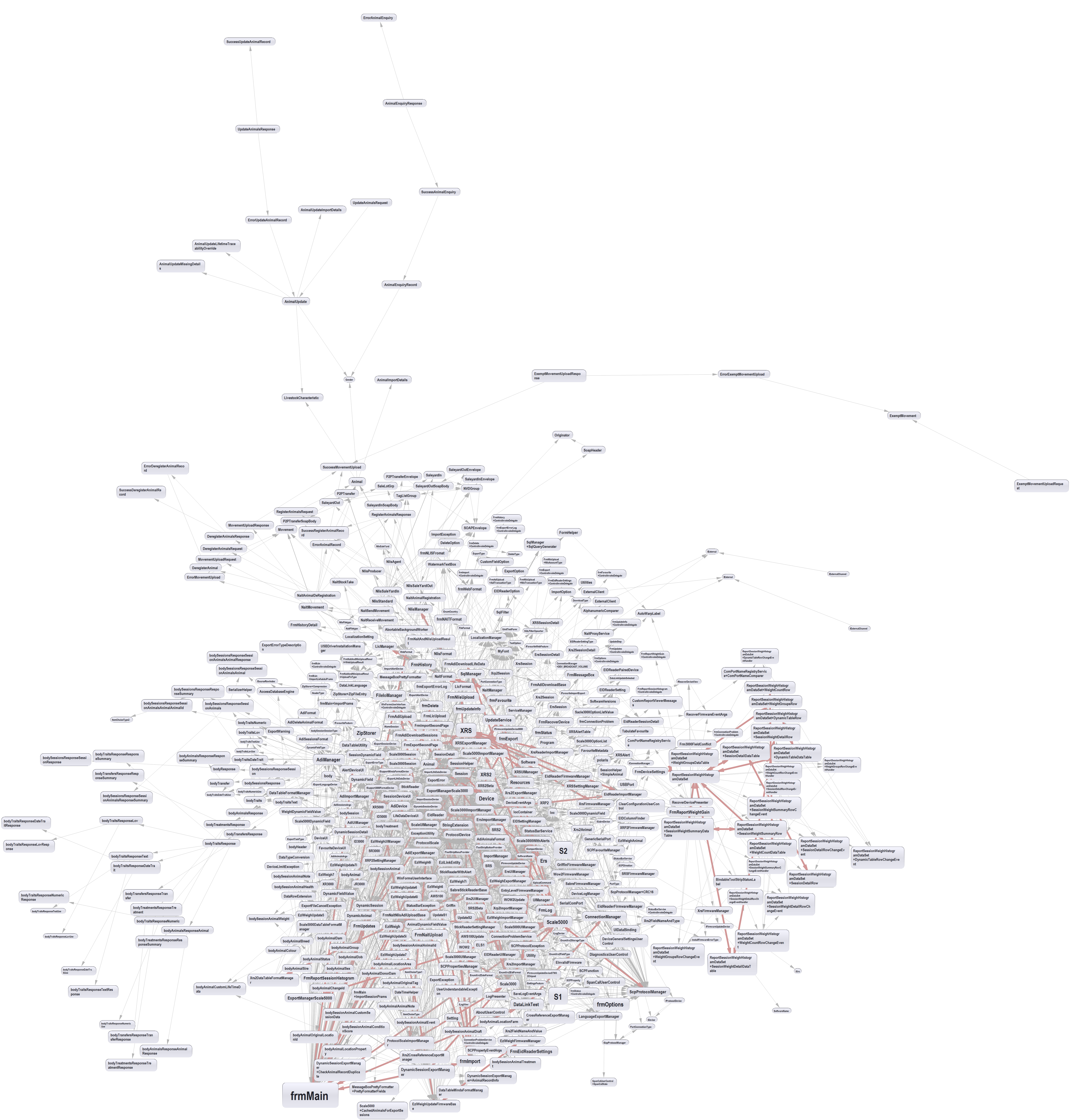
This graph is very large. Right click on it, and open it in a new tab in your browser, so you can zoom in to see the dependencies in the background. It is truly frightening. Ndepend had no chance to find the dependency layers. There may be vague onion type layers going outwards from the middle. It makes readily visible why continued maintenance on this application is so difficult. You have to read a lot of code to find even a tiny part of this hidden structure.
The developer who maintains the application tells me this is a fair reflection of the complexity that he has to deal with.
To be fair, some of the dependencies in this diagram are 'good' dependencies (as described in an earlier section on good and bad dependencies). For example, the box near south-east called ScpProtocolManager has a lot of dependencies coming into it, which means it is possibly used a lot and therefore is potentially good abstraction. Ndepend does not know about the concept of good and bad dependencies, but if it did I would have it just display the bad ones.
3.12.2. New ALA application dependency graphs
Here is the equivalent Ndepend generated class dependency graph for the new ALA version of the application. This graph has the classes from all namespaces.
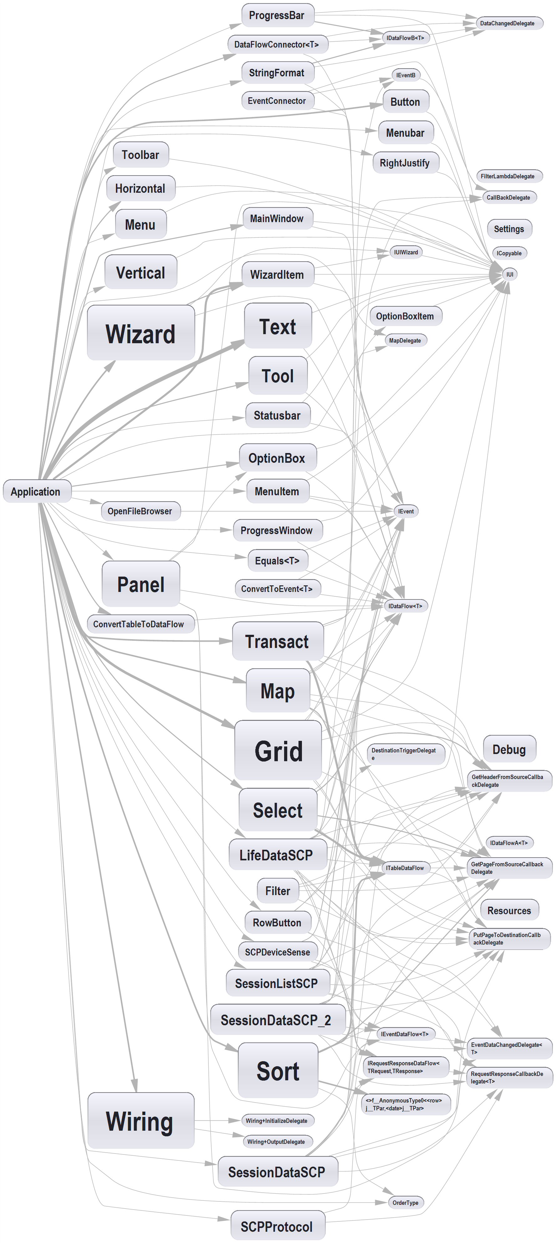
You can see the three ALA layers which are vertical and go from left to right. Only the Application sits in the top layer. The DomainAbstractions layer contains the next two columns of classes and a few from the next column. And the ProgrammingParadigms layer contains the rest on the right. Actually there were a couple of bad dependencies present when this graph was generated which have since been fixed. (There should be no dependency between Panel and OptionBox, nor between Wizard and WizardItem.) With these removed, the graph would form into the three abstraction layers.
The newly rewritten application is a work in progress at this point. However, as features are added, this is all the dependencies you will ever see. The Application already uses most of the domain abstractions we will ever need, and the domain abstractions already use the programming paradigm interfaces they need. There are a few DomainAbstractions to be added, but this is essentially what the class dependency graph will stay looking like.
As of this writing, the new ALA version of the application is still a research project, but so far everything has gone smoothly with two weeks spent doing the description of the requirements as a diagram, and 18 months so far spent writing the domain abstractions. So far there are no issues getting it to actually execute. It is expected that we will actually commercialize the project soon and replace the old application.
3.12.3. The application’s diagram
As we said in this chapter, diagrams can be an important aspect of ALA when the user story naturally contains a network of relationships among its instances of abstractions. In this application this is the case. There are UI relationships between elements of the UI. There are dataflow relationships between UI elements, data processing elements, and data sources. There are event-flows from UI to wizards and between wizards and the SaveFileBrowser. and there are minor dataflows such as a the filepath from the file browser to the csvFileReaderWriter.
Here is a sample section from the application diagram that shows all the relationships that implement the user story:

This diagram was drawn using Xmind. It shows a single user story. There is a UI with a menu item or a tool bar to start the user story. It then displays a browse dialogue to specify the location of the file. When the filepath has been selected, it gets data off a device on a COM port, using a protocol, and writes it to a CSV file. The data is also routed to be shown on a grid on the UI.
The user story diagram makes use of four different programming paradigms (which become four different interface types). Firstly there is the UI structure consisting of the window with its menubar, grid etc arranged inside it. Secondly, there is an event connection for when the menu is clicked which opens the browse dialog. Thirdly a dataflow connection carries the output of the browse dialog, a string containing the selected filepath, to the CSVFileReaderWriter. Another dataflow connection carries characters between the COM port and the SCPProtocol and another carries SCPcommands from the SessionDataSCP. The forth programming paradigm is a table dataflow that carries dynamic columns and rows of data from the SessionDataSCP object to the grid object in the UI and to the CSVFileReaderWriter.
Having drawn the diagram to represent the user story, we need to make the diagram execute. When we started this particular project we had no tool for automatically generating the code from the diagram, but during the project, one of the interns wrote a tool to do this. It parsed the Json output from Xmind and generated C# wiring code equivalent to what we will show below.
However, at first we were hand generating code, and it is instructive to know what this hand generated code looks like, just so we know how the diagram actually executes.
When we were hand generating the code, it was important that the code was readable from the point of view of seeing how it corresponds exactly with the diagram. (It wasn’t important that the code was readable from the point of view of seeing how the user story works - that was the job of the diagram.) We had various conventions to support the one to one matching of diagram and code. One of these conventions was to indent the code to exactly mirror the tree structures in the diagram. Another was that whenever a new instance of an abstraction instantiated, all its ports would be wired immediately, and they would be wired in the order they were declared in the abstraction. This implies a depth first wiring strategy, analogous to walking the diagram tree depth first. Any ports with cross connections (the red lines in the diagram) would also be wired to their destinations at the time the abstraction were instantiated. If the destination instance did not already exist it would be pre-instantiated.
Using these conventions, it is a simple matter to hand generate the code below from the diagram.
using System;
using System.Windows.Media;
using DomainAbstractions;
using Wiring;


namespace Application
{
    class Application
    {
        private MainWindow mainWindow = new MainWindow("App Name") { Icon = "XYZCompanyIcon"};

        [STAThread]
        public static void Main()
        {
            new Application().Initialize().mainWindow.Run();
        }

        private Application Initialize()
        {
            return this;
        }

        private Application()
        {
            var getInfoWizard = new Wizard("Get information off device") { SecondTitle = "What information do you want to get off the device?" };
            Grid DataGrid;
            var sessionDataSCP = new SessionDataSCP();
            var csvFileReaderWriter = new CSVFileReaderWriter();

            mainWindow
            // UI
                .WireTo(new Vertical()
                    .WireTo(new Menubar()
                        // XR3000
                        .WireTo(new Menu("File")
                            .WireTo(new MenuItem("Get information off device") { Icon = "GetDeviceIcon.png", ToolTip = "Get session data or LifeData or favourites from the device\nto save to a file or send to the cloud" }
                                .WireTo(getInfoWizard)
                            )
                            .WireTo(new MenuItem("Put information onto device") { Icon = "PutDeviceIcon.png" })
                            .WireTo(new MenuItem("Exit") { Icon = "ExitIcon.png" })
                        )
                        .WireTo(new Menu("Tools"))
                        .WireTo(new Menu("Help"))
                    )
                    .WireTo(new Toolbar()
                        // XR3000
                        .WireTo(new Tool("GetDeviceIcon.png") { ToolTip = "Get information off device" }
                            .WireTo(getInfoWizard)
                        )
                        .WireTo(new Tool("PutDeviceIcon.png") { ToolTip = "Put information onto device" })
                        .WireTo(new Tool("DeleteDeviceIcon.png") { ToolTip = "Delete information off device" })
                    )
                    .WireTo(new Horizontal()
                        .WireTo(new Grid() { InstanceName = "Sessions" })
                        .WireTo((DataGrid = new Grid() { InstanceName = "DataGrid" })
                            .WireFrom(sessionDataSCP)
                        )
                    )
                    .WireTo(new Statusbar()
                        .WireTo(new Text() { Color = Brushes.Green }
                            .WireFrom(new LiteralString("Connected to device"))
                        )
                    )
                );


            getInfoWizard
                .WireTo(new WizardItem("Get selected session files") { Icon = "IconSession.png", Checked = true }
                    .WireTo(new Wizard("Select destination") { SecondTitle = "What do you want to do with the session files?", ShowBackButton = true }
                        .WireTo(new WizardItem("Save selected sessions as files on the PC") { Icon = "SessionDocumentIcon.png", Checked = true }
                            .WireTo(new SaveFileBrowser("Select location to save data") { Icon = "SaveIcon.png", InitialPath = "%ProgramData%\XYZCompany"}
                                .WireTo(csvFileReaderWriter)
                            )
                        )
                        .WireTo(new WizardItem("Send records to NAIT") { Icon = "NAIT.png" })
                        .WireTo(new WizardItem("Send sessions to NLIS") { Icon = "NLIS.png" })
                    )
                    .WireTo(getInfoWizard)
                )
                .WireTo(new WizardItem("Get Lifedata"));

            var comPorts =
                new ComPortAdapter()
                    .WireTo(new SCPProtocol()
                        .WireTo(new SessionDataSCP()
                            .WireTo(DataGrid)
                            .WireTo(csvFileReaderWriter)
                        )

                    );

        }
    }
}
We used a 'diagram first' rule to keep the diagram and code in sync. Change the diagram first, then change the wiring code.
As of this writing, a graphical IDE is being developed for these types of ALA applications.
4. Chapter four - Execution models.
4.1. Introduction to programming paradigms
ALA fundamentally begins with the premise of using abstractions to achieve zero coupling at design-time. Zero coupling is preserved if relations between abstractions are always in the direction of greater abstraction. Thus abstraction layers emerge, with each layer significantly more abstract than the one above. It is interesting to observe how these layers seem to emerge typical usage patterns, which in turn give rise to their names: Application layer, User stories layer, Domain abstractions layer, Programming Paradigms layer, and so on.
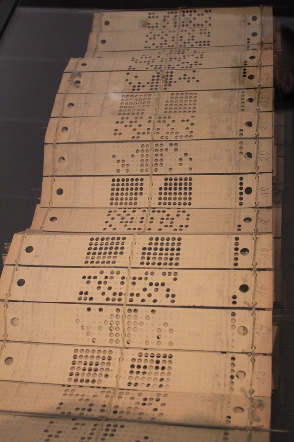
The layer below the domain abstractions is really interesting in this respect. When we compose or wire two or more instances of domain abstractions together, we need that to have a meaning. Here are some common examples:
-
Imperative ((sequential activities in computer time)
-
event driven
-
dataflow
-
UI layout
-
activity flow (sequential activities in real time)
-
state machine transition
-
state machine substate
-
data schema
These are all quite abstract concepts. They have great potential for reuse. We call them programming paradigms because each is a different way of thinking about programming. Each gives different meaning to composition. We call the layer they go in programming paradigms.
It is an essential part of ALA that we can use multiple programming paradigms in the same user story. In ALA, user stories (or features) are cohesive abstractions. To completely describe a user story, common programming paradigms needed may be UI layout, dataflow, activity and data schema. This use of multiple programming paradigm is referred to as polyglot programming paradigms.
The programming paradigms layer may also contain other abstractions useful for building domain abstractions, but are not used as relationships between instances of abstractions. Examples are the concepts of 'Persistence' or 'Styles'. In this chapter we will be concentrating on programming paradigms used to compose instances of domain abstractions, and showing the ways they actually execute, which is called their execution model.
Here is Peter Van Roy’s taxonomy of programming paradigms which gives us an idea of what the term "programming paradigm" means in general. Peter Von Roy is an advocate for multiple programming paradigms in a computer language, which is why the language Oz appears all over the diagram. In ALA we invent and implement our own programming paradigms, without relying on them being built into the underlying programming language.
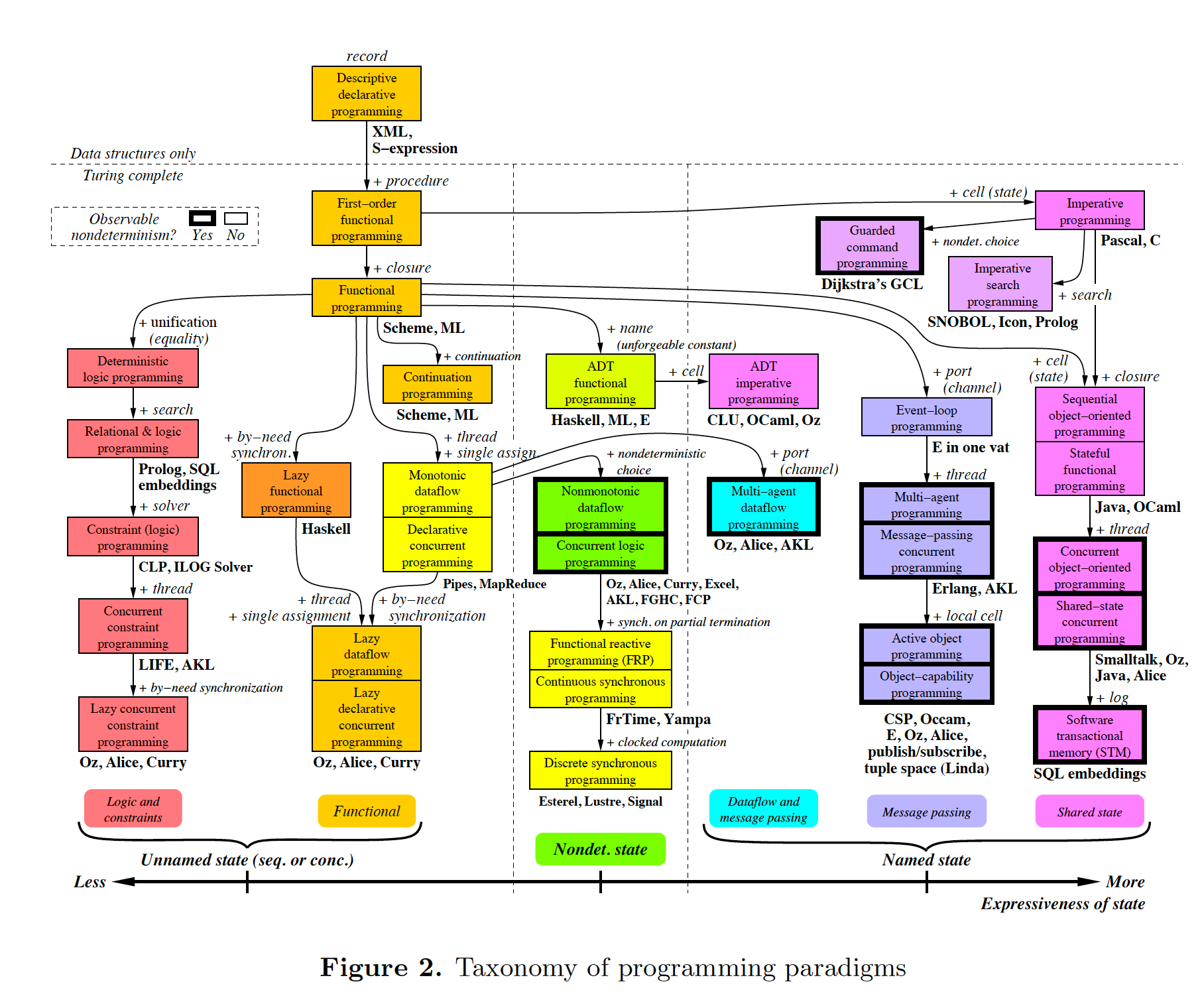
|
In ALA "programming paradigms" are used to compose instances of domain abstractions. The programming paradigm provides "the meaning of composition". |
Programming paradigms are by no means limited to the ones discussed in this chapter. Custom ones can be invented as needed (when they allow better expression of the requirements). We do this with the example at the end of this chapter for scoring games such as Bowling or Tennis. We use a 'ConsistsOf' programming paradigm which allows us to express that a match consists of sets, a set consists of games, and so on.
4.2. Introduction to execution models
Programming paradigms and execution models are closely related but not precisely the same thing. Programming paradigms are the meaning of composition. Execution models are how we make that meaning actually work. Essentially, the execution model is how the underlying imperative programming paradigm of the CPU is going implement the new programming paradigm.
Some programming paradigms can have simple execution models. They can be implemented with an interface with one method. The simplest example of this is the synchronous event programming paradigm:
namespace ProgrammingParadigms
{
    interface IEvent
    {
        void Send();
    }
}
Such an interface looks like it adds nothing, but it transforms programming to a paradigm of composing instances of abstractions in an infinite variety of possible ways.
Ports use instances of these interfaces. Essentially the interface allows any output port using this paradigm to be wired to any input port using this paradigm.
Other programming paradigms may require an engine or framework. Possible ways these execution models could work is discussed under each programming paradigm in this chapter.
4.3. Coding execution models
Here we just show simple code examples for two execution models for the event driven programming paradigm to get a grounding at the code level.
4.3.1. Synchronous events
The interface for synchronous events was given just above.
The difference between this and your everyday common imperative function call or method call is only the indirection. The sender doesn’t know who it’s calling. (In conventional code, indirection creates problems, but in ALA these problems do not exist, so all communications use this type of indirection. This is discussed further later.)
First let’s create two dummy domain abstractions with ports using the synchronous event driven programming paradigm. The two domain abstractions will use and implement this interface respectively:
using System;
using ProgrammingParadigms;

namespace DomainAbstractions
{
    class A
    {
        private IEvent output; (1)

        public void start()
        {
            Console.WriteLine("1");
            output?.Send();
            Console.WriteLine("3");
        }
    }
}| 1 | The output port is a private field of type interface |
using System;
using ProgrammingParadigms;

namespace DomainAbstractions
{
    class B : IEvent (2)
    {
        // input port
        void IEvent.Send()
        {
            Console.WriteLine("2");
        }
    }
}| 1 | The input port is an implemented interface |
Now we can write an application that wires an instance of A to an instance of B.
using System;
using DomainAbstractions;
using ProgrammingParadigms;
using Foundation;

namespace Application
{
    class Application
    {
        static void Main(string[] args)
        {
            var program = new A().WireTo(new B()); (1)
            program.start();
        }
    }
}| 1 | The meat of the application wires an instance of class A to an instance of class B. |
The output of the program is "123".
The Main function instantiates one instance of each of our domain abstractions, and wires them together. (If you have not seen the WireTo abstraction before, it is an extension method that uses reflection to search in class A for a private variable with a type that is an interface. It then sets it pointing to the instance of B if B implements the interface. WireTo is not central to the current discussion, the IEvent interface is. WireTo is discussed in more detail in the example projects of chapters two and three.)
Notice just how abstract IEvent is. It’s highly reusable. It’s not specific to any domain abstraction or the application. It just knows how to transmit/receive an event. Because it is so abstract, it is stable. The more domain abstractions that depend on it the better, as that will allow them to be wired together in arbitrary ways, which gives us composability.
The IEvent interface can be compared with the observer pattern (publish/subscribe) which also claims to achieve decoupling. However the observer pattern only reverses the dependency of a normal method call. Instead of the sender knowing about the receiver, the receiver knows about the sender (when it registers for the event). If the sender and receivers are peers in the same layer, the observer pattern does not solve the problem. The IEvent interface decouples in both directions. The job of 'subscribing' is moved to the application layer, because only the application should have the knowledge of what should be wired with what.
4.3.2. Asynchronous events (the event loop)
In the above example, we used the word event, but implemented it in a specific way (a synchronous method call). The terms event and event driven may have overloaded meanings. To some it may mean asynchronous or it may mean observer pattern (an event is a public thing you can subscribe to), or it may mean both.
In ALA the term means neither of these. As a programming paradigm it simply means that we think of programming as reacting to what happens instead of prescribing what will happen next - a reactive rather than prescriptive programming style. They can be either synchronous or asynchronous. They are never public - the layer above always wires them up from point to point explicitly. Events can be wired to fan-in or fan-out.
We discuss the meaning of synchronous and asynchronous in more depth later, but here we just want to see how asynchronous can be implemented at the code level. Synchronous and asynchronous are two different execution models for the same programming paradigm.
To implement the asynchronous execution model, conventional code may use an event loop that works something like this: the originator of the event calls a Send method on an EventLoop object. It passes a reference to a function or method of another object that it wants to send the event to. The Send method in EventLoop creates an object that represents the event and puts it into a queue. The Send method then returns. The main loop resides in this EventLoop object. It loops taking events from the queue one at a time and calls the referenced function or method. This is sometimes called the reactor pattern, but its actually a simplified version of reactor so we will call it simply an event loop.
For ALA, the only difference is that the sender can not specify the receiver function and object.
Here is the application layer code:
using System;
using DomainAbstractions;
using ProgrammingParadigms;
using Foundation;

namespace Application
{
    class Application
    {
        static void Main(string[] args)
        {
            // instantiate an asynchronous execution model
            var eventLoop = new EventLoop();

            // Wire using the asynchronous execution model
            var program = new A().WireTo(new B(), eventLoop); (1)
            program.Start();

            eventLoop.Start();
        }
    }
}| 1 | The meat of the application wires an instance of class A to an instance of class B. |
The difference with our previous synchronous application is that we first spin up an asynchronous execution engine object called eventLoop. The WireTo is used in the same way except that we pass in the execution model.
Here are the A and B dummy domain abstractions again. They are identical to the ones we used for the synchronous version above.
using System;
using ProgrammingParadigms;

namespace DomainAbstractions
{
    class A
    {
        private IEvent output;

        public void Start()
        {
            Console.WriteLine("1");
            output?.Send();
            Console.WriteLine("3");
        }
    }
}using System;
using ProgrammingParadigms;
namespace DomainAbstractions
{
class B : IEvent
{
// input port
void IEvent.Send()
{
Console.WriteLine("2");
}
}
}When this program runs, it will print "132" instead of the "123" that the synchronous version did. At the domain abstraction level, we need to not care whether it is "123", or "132". If we do care, then we need to use a different programming paradigm.
Now let’s have a look at the programming paradigm abstraction to see how it works.
using System.Collections.Generic;
using Foundation;

namespace ProgrammingParadigms
{
    public interface IEvent (1)
    {
        void Send();
    }


    static class EventLoopExtensionMethod (2)
    {
        public static T WireTo<T>(this T A, object B, EventLoop engine, string APortName = null)
        {
            engine.WireTo(A, B, APortName);
            return A;
        }
    }


    class EventLoop
    {

        private List<IEvent> queue = new List<IEvent>(); (3)

        public void WireTo(object A, object B, string APortName) (4)
        {
            A.WireTo(new Intermediary(this, (IEvent)B), APortName);
        }

        public void Start()
        {

            while (!Console.KeyAvailable)
            {
                if (queue.Count > 0)
                {
                    IEvent receiver = queue[0];
                    queue.RemoveAt(0);
                    receiver?.Send();
                }
            }
        }


        private class Intermediary : IEvent
        {
            private IEvent receiver;
            private EventLoop outerClass; // needed to access our outer class instance

            public Intermediary(EventLoop outerClass, IEvent receiver)
            {
                this.receiver = receiver;
                this.outerClass = outerClass;
            }

            void IEvent.Send() (5)
            {
                outerClass.queue.Add(receiver);
            }
        }
    }
}| 1 | The abstraction begins with the interface itself, which is unchanged from the synchronous version. |
| 2 | Overload of the WireTo extension method. We want an extension method so that we can wire things up using the same fluent syntax as the standard WireTo. This WireTo overload differs from the usual WireTo by the extra parameter for passing in the AysnchronousEventLoop instance. The method simply defers to the WireTo method in the EventLoop class. |
This mechanism of overloading the WireTo method can be used by any programming paradigm.
| 1 | The EventLoop class keeps a list of events waiting for execution. |
| 2 | Unlike for the synchronous case, the sender’s port is not wired directly to the receiver’s port. An intermediary object is wired in-between. The class for the intermediary object is inside the EventLoop class as we don’t want it to be a public part of the EventLoop abstraction. |
The WireTo method instantiates an intermediary object, stores the receiver object cast as the interface into it (which is effectively wiring the intermediary to the receiver), and then calls the standard WireTo in the Foundation layer to wire the sender to the intermediary object.
| 1 | When the sender calls Send on its output port, the intermediary object intercepts the synchronous call. The intermediary object queues the call in the EventLoop class and immediately returns. It actually queues the reference to the interface of the receiver. |
| 2 | The EventLoop class has a loop that takes the references to receiver objects out of the queue one at a time, and calls the IEvent’s Send method in the receiver. |
In this example we have put the main loop inside the execution model for simplicity. We would not normally do this because we may have several different programming paradigms each with their own main loops. So we could have the main loop in the Foundation layer, and the different execution models would register a Poll method on it. Alternatively we could make the loop function an async function that awaits on an awaitable queue implementation.
As usual in ALA, we do not try to decouple anything inside the AsynchronousEvent.c abstraction. Everything in it cohesively works together.
The propose of the examples is to show that we can create our own programming paradigms and that their implementation can be simple.
4.4. Execution model properties
Now that we have the idea of what we mean by programming paradigms and execution models at the code level, we next need to discuss some general properties of execution models, such as direct vs indirect, synchronous vs asynchronous, push vs pull, etc. we will refer to these properties when discussing specific execution models later.
In conventional imperative code, the execution model is inherently synchronous in the use of the function or method call. In ALA we have free choices for execution models. Also in conventional code, one of the forces is managing dependencies. This can influence the execution model. For example we might pull for a dependency reason even though we would rather push for a performance reason. In ALA, wiring does not involve dependencies, so we are free to focus on other design choices with respect to execution models.
In this section we will try to clarify what these design choices are for programming paradigms that mean communication. We will note the forces on these design choices.
4.4.1. Sideways vs down vs up communications
In conventional code, communications generally follow dependencies directly. If we try to think in terms of layers, with dependencies always going down the layers, these communications always go either up or down. So we may not be used to thinking of sideways communications. Or if we do allow sideways dependencies within a layer, we may not be used to thinking about sideways communications and up/down communications as different things.
In ALA, we need to think of them differently. Let’s refer to sideways communications as wired-communications, and up/down communications as abstraction-use-communications.
A common example of abstraction-use communication is when you configure an instance of an abstraction by passing parameters to the constructor, or by calling setters. Another example is calling a squareroot function in your math library. A common example of upward communication using abstraction-use-communication is executing a lambda expression that has previously been passed in to an instance of an abstraction during its configuration. Upward calls are always indirect in some way, such as the mentioned lambda expression, passing in an anonymous or named function, observer pattern (publish subscribe), callback, or strategy pattern. We don’t use virtual functions in ALA for up calling because we don’t need or want to use inheritance.
A common example of wired-communications is when an instance of an abstracton sends something out on a port. It arrives at the input port of another instance of an abstraction to which it was wired by the layer above.
In all the following discussions of programming paradigms, we will be talking about wired-communications unless noted otherwise. Note that we use the word communications to cover for both events and dataflow types of programming paradigms. Another common term is message.
4.4.2. Indirect function calling
Sideways communications in ALA is always indirect. The sender never names the receiver or the function or method in that receiver. Conversely, receivers never register themselves to a sender, or to a public event. Global event names are never used. Communications always follows the wiring put in place by the layer above.
In conventional code, there is a downside associated with indirection, which is tha it becomes harder to follow the flow of execution through the modules for a given user story. That downside does not exist for ALA. In fact it is the opposite - it is easier to trace the flow of calls through the system. This is because user stories are expressed in one place cohesively. You see all the explicit wiring of a user story abstraction in one place instead of tracing it through multiple modules. Only if an abstraction it uses does something unexpected do you need to drop down inside the abstraction, and enter a different self-contained self-cohesive set of code.
When reading code inside an abstraction, it is in the very nature of abstractions that they know nothing of the outside world. They do not need or want to know where events come from or go to externally. Indirection is used so that flow can lift out of the internals of an abstraction to the more specific wiring code in a layer above.
Even synchronous function calls are always indirect. At run-time, the inside of one abstraction synchronously calls a method inside another abstraction under the direction of the wiring in the layer above. But at design-tie, it has no knowledge of what that other abstraction or method is. Whether the run-time execution model is synchronous or asynchronous, push or pull, with fan-out or fan-in, the wiring model between instances of abstractions with ports is always indirect.
Even if the communications is asynchronous, the caller does not send the event to a particular destination, nor does it give the event a global name so that receivers can register to it. Both patterns would involve a bad dependency. Instead it still only goes as far as its own output port.
Conventional code will often use an interface or the observer pattern (publish-subscribe) (or C# events) to invert a dependency. If the two modules were peers in the same layer, inverting the dependency by adding an indirection only makes the program even more difficult to follow. ALA does not need to use the dependency inversion principle or the observer pattern for peer to peer communications because there is no dependency. In other words ALA completely sidesteps the dependency inversion principle and the observer pattern for all communications between peers.
ALA generally uses dependency injection directed by explicit wiring.
Having said that ALA does not use the observer pattern (or any other form of the receiver subscribing to senders in the same layer), the observer pattern is sometimes used within a programming paradigm interface. Consider a programming paradigm where communications is needed in both directions. In the same direction as the wiring, it is usually implemented as a simple method call. The way interfaces work in our programming languages, the A end uses the interface and the B end implements it. The asymmetry is a shame. If we want a method call in the other direction, we use the observer pattern inside the interface. The publisher, the B end, implements the observer pattern. The subscriber, the A end, subscribes to it. The difference from the standard observer pattern is that the subscriber does not know the publisher. It is only subscribing to it indirectly via the interface.
If a dependency were going up from one abstraction layer to a higher one, then of course we invert the dependency. But a dependency from a more abstract abstraction to a more specific one doesn’t make sense in the first place and so this situation never occurs. The dependency inversion principle is already built into the ALA constraints, so you never need to invert dependencies later.
4.4.3. Push vs pull
If we are using standard synchronous function calls or method calls as the execution model, we have a choice between push and pull. In other words, does the sender of an event or data initiate the call, or does the receiver?
Push
Send(data);Pull
data = Receive();In conventional code, the decision as to whether to use push or pull is often dictated by the need to control the direction of dependencies. To change a pull to a push without reversing the dependency would require indirection or the observer pattern. Similarly, to change a push to a pull without reversing the dependency would require an indirection. So usually we use the one that allows us to use a simple function call with the dependency in the desired direction.
With ALA, most run-time communications take place within a layer, and there are no dependendencies between the abstractions involved. Instances of abstractions are wired using interfaces that represent programming paradigms:
namespace ProgrammingParadigms
{
    interface IDataflow<T>
    {
        void Push(T data);
    }
}namespace ProgrammingParadigms
{
interface IDataflowPull<T>
{
T Pull();
}
}Because there are no dependency constraints, we are free to choose between push and pull. Usually it would be for performance reasons. If the source data changes infrequently we would use push. If source data changes frequently, and the receiver only needs the value infrequently, we could choose to use pull.
An example of pull is getting data from a database. Pulling is the only choice that makes sense because any particular data is needed so infrequently. And pushing is the only sensible choice for putting data into a database. For this reason, in conventional code, the dependency is almost always towards the database. This is not the desired direction. Clean architecture reverses this dependency. But we don't want the reverse dependency either. So clean architecture will use a set of adapters that have dependencies both on the business logic interfaces and the database. ALA uses no dependencies on the business logic. In effect it will use a single adapter with dependencies on both a programming paradigm interface and the database.
It would be nice if you could choose between push and pull at wiring time. In other words, we design domain abstraction ports to handle both push or pull, and you choose push or pull when wiring instances in the application. For example a signal filter could support both push and pull. If not we might need two version of the filter. Unfortunately it increases the amount of code inside the abstractions. So we usually write abstraction ports to use either push or pull.
To allow optimal composability of abstractions, I use push ports by default so that most ports can be wired directly. Push also works quite naturally for events. It means that the initiator of an event pushes it as soon as it happens. The opposite is possible: receivers poll the source when they are interested to know if an event has occurred.
For dataflows, push means that the data 'flows' whenever it changes. This works better performance-wise if the data does not change too frequently. It works well when all data must be processed. It is ok when all the data does not need to be processed, and only the latest data is important. Push is usually more efficient than periodically polling for data.
A final factor in the preference to use push by default is that push ports can be wired for either synchronous or asynchronous execution models without changing the domain abstractions (discussed above in the section on synchronous vs asynchronous). To allow this for pull ports requires the pull end to be written for an asynchronous execution model, which can be awkward. This aspect is discussed more fully in the section on the request/response programming paradigm later.
For all the above reasons we use push ports by default, and pull ports when we have to. It is analogous to using RX (reactive extensions).
Remember we are talking about 1-way communcations. In a later section we discuss programming paradigms that use 2-way communications.
Wiring incompatible push & pull ports
It is possible to wire together instances of domain abstractions that have incompatible ports with respect to push and pull, provided the communications becomes asynchronous. A send port that uses push can be wired to a receive port that uses pull. And a send port that uses pull can be wired to a receive port that uses push. This can even be done automatically, so that the user story doing the wiring does not need to worry about it.
For the case of a push send port being wired to a pull receive port, the wiring system detects this situation and wires in an intermediary object which is an instance of a simple buffer abstraction. If the paradigm is simple events, the abstraction stores a flag for whether or not the event has been sent. When the receiver pulls the event, it clears the flag.
For the case of a pull send port being wired to a push receive port, the wiring system detects this situation and wires in an intermediary object which is an instance of a simple polling abstraction. This instance is configured with a default polling rate. It polls the sender periodically to see if the event has occurred, and then calls the receiver if it has. For dataflow, it calls the sender periodically, and then calls the receiver at least once and thereafter whenever the data changes.
A situation where a sender may want to have a pull port is a driver that gets data from the outside world. The driver doesn’t want the responsibility of controlling when the external read takes place. So it will use a pull port so it reads at a time determined by the user story. The user story will either configure the polling rate of the intermediary or configure an active object somewhere that will pull the data when needed.
Another situation to use pull is where the sender is completely passive or lazy. For example, it doesn’t want to execute a computationally expensive routine until the output is needed.
Another situation where a pull port makes sense is an abstraction with many inputs. We want the abstraction to react when a specific port receives data or an event. If we don’t want to buffer the data coming in on other inputs internally in the abstraction, we can just make them pull ports. If they need to be wired to push ports, then intermediary buffer objects would be wired in.
When a sender with a push port is wired to a receiver with a pull port using a buffer intermediary object, a situation can arise where the sender produces data faster than the receiver consumes it. In some cases this wont matter. In other cases the user story has the knowledge of how to resolve the situation. It can wire in an averager or filter abstraction. If the receiver must process all the data, and the sender produces data only in bursts, the user story can wire in a FIFO abstraction to smooth out the rate of data. The Fifo can have a reverse flow control channel that tells the source when to stop and start so the fio doesn’t overflow. If none of these solutions work, the user story can wire in a load splitter to multiple receivers.
If pull ports are quite common, we may then want 'pull' versions of some domain abstractions. For example, we may need a filter abstraction to have a pull variant.
In summary, I use push ports for domain abstractions by default. In situations where this doesn’t suit I can still use pull ports. When incompatible ports need to be wired, then a variety of intermediary objects can be wired in to solve the issues without having to change the sender or receiver abstractions.
4.4.4. Fan-in, fan-out wiring
In chapter three, we used the terms fan-in and fan-out in relation to dependencies down layers. Here the terms fan-in and fan-out are used for something completely different. Here we are talking about wiring.
Fan-out means that an output port of one instance of an abstraction is wired to many instances. Fan-in means many instances are wired to a single input port. It depends on what makes sense for each particular programming paradigm.
Fan-out implementation
Some programming paradigms support fan-out out of the box. An example is the UI programming paradigm. Many UI domain abstractions have a list port for child UI elements. The WireTo can wire directly from this port to multiple instances of other UI elements.
Most output ports of domain abstractions for other programming paradigms do not use a list for their output ports, so they do not directly support fanout. This is because they are usually wired one point. If they used a list, then the domain abstraction internal code would need to use a for loop to output to every instance in the list. We can still do fanout using an intermediary object. This intermediary object simply contains the needed for loop. An example of such an intermediary for the Dataflow programming paradigm is:
/// <summary>
/// DataFlowFanout has multiple uses:
/// 1) Allows fanout from an output port
/// 2) If the runtime order of fanout dataflow execution is important, DataFlowFanout instances can be chained using the Last port, making the order explicit.
/// 3) Allows an abstraction to have multiple input ports of the same type. (A C# class can implement a given type of interface only once.)
/// --------------------------------------------------------------------------------
/// Ports:
/// 1. IDataFlow<T> implemented interface: incoming data port
/// 2. List<IDataFlow<T>> fanoutList: output port that can be wired to many places
/// 3. IDataFlow<T> last: output port that will output after the fanoutList and IDataFlow_B data changed event.
/// 4. IDataFlow_B<T> implemented interface: ouput port but is wired opposite way from normal.
/// </summary>

public class DataFlowFanout<T> : IDataFlow<T>, IDataFlowPull<T>, IDataFlow_R<T>  (1) (2) (3)
// input, pull output, push output
{
    // properties
    public string InstanceName = "";

    // ports
    private List<IDataFlow<T>> fanoutList = new List<IDataFlow<T>>(); (4)
    // ouptut port that supports multiple wiring

    private IDataFlow<T> Last; (5)
    // output port that outputs after all other outputs to allow controlling order of execution through chaining instances of these connectors.


    // IDataFlow<T> implementation (input) ---------------------------------
    void IDataFlow<T>.Push(T data) (6) (7)
    {
        this.data = data; // buffer the data in case its needed by the pull output
        foreach (var f in fanoutList) f.Push(data);
        push_R?.Invoke(data);
        Last?.Push(data); (5)
    }

    // IDataFlowPull<T> implementation ---------------------------------
    private T data = default;  // used to buffer data for later pull on the output port
    T IDataFlowPull<T>.Pull() { return data; } (7)

    // IDataFlow_R<T> implementation ---------------------------------
    // make explicit so it's not visible without using the interface
    private event PushDelegate<T> push_R;
    event PushDelegate<T> IDataFlow_R<T>.Push { add { push_R += value; } remove { push_R -= value; } } (7)
}| 1 | IDataFlow<T> is the input port |
| 2 | IDataFlowPull is an output port (purpose discussed later) |
| 3 | IDataFlow_R is an output port (purpose discussed later) |
| 4 | Output port that’s a list to support fan-out. WireTo will wire it any number of times. |
| 5 | Output port called Last (purpose discussed later) |
| 6 | Implementation of the input port. When data arrives at the input, it outputs the data directly to all the different output ports, including to every destination in the fanout output port list. |
| 7 | All implemented interfaces are implemented explicitly in C# (not implicitly). There are two reasons for this in ALA: 1) We only want the interface’s method/event to be visible through a reference to the interface, not the public interface of the class. The public interface of the class is for the layer above to create and configure objects of the class. It generally has no need to access the ports of the class at run-time, and if it did we would want to cast to the interface to make that clear. 2) If there were two interfaces using the same method name or same event delegate, we will want to implement them separately. |
Fan-out ordering
The need for fan-out in the wiring is common for many programming paradigms. The order of the synchronous calls to the different fan-out destinations may or may not be significant. Only the layer above doing the wiring knows if the order is significant. Sometimes it is sufficient for the order to be defined as the order they are wired in, or ’down’ in a diagram. The UI fanout works this way to control top to bottom or left to right UI layouts. This is a satisfactory way to define order in a UI.
For events or Dataflows, this is not considered explicit enough. Where order matters, we should use ”Activity Flow” (exactly analogous to UML activity diagrams) to control ordering. The order can be controlled by using a chain of DataFlowFanout instances. DataFlowFanout has a port called Last which facilitate this chaining. Last is invoked after all other output ports.
| 1 | The Last port can be seen in the DataFlowFanout listing given above. |
4.4.5. Work around for multiple inputs of the same type
C# and other languages don’t allow an interface to be implemented more than once. Sine we use interfaces as ports in ALA, this can be a serious limitation.
For example, consider implementing an AND gate with 4 inputs all IDataFlow<bool>.
    public class AndGate : IDataFlow<bool>, IDataFlow<bool>, IDataFlow<bool>, IDataFlow<bool>
    {
    }
Implementing IDataFlow<bool> more than once like that gives a compiler error.
It’s a valid thing to do however. I can only assume that outside of ALA, no one seems to have needed it. In fact the whole concept of ports should be part of all object oriented languages. Only then would OOP realize it’s potential for reuse. (ALA is really just OOP done right.)
If the C# language allowed the same interface to be implemented multiple times, the only syntactical difference would be that the implementations would be given names:
    // We want to do this, but can't in C#
    public class AndGate : IDataFlow<bool> Input1, IDataFlow<bool> Input2, IDataFlow<bool> Input3, IDataFlow<bool> Input4
    {
        void Input1.Push(bool data)
        {
        }
    }
You would be able to set a reference to the object’s interface using this name instead of casting to the interface type.
// We want to do this, but can't in C#
var ag = new AndGate();
IDataFlow<bool> referenceToInput1 = ag.Input1;
Java almost allows this to be done using method references. But it only works when there is one method in the interface.
We already used a work-around for this limitation of C# in the Add domain abstraction in chapter 2. In that work-around we created a Double2 type which was a simple struct containing a double. That allowed us to implement both IDataFlow<double> and IDataFlow<Double2>. But it’s not a general solution.
A more general work-around for this limitation of C# is to use interface fields instead of interface implementations and reverse the wiring.
    IDataFlow_R<bool> Input1;
    IDataFlow_R<bool> Input2;
    IDataFlow_R<bool> Input3;
    IDataFlow_R<bool> Input4;
We append an "_R" to the name of the interface to indicate it is a 'reversed wired' interface. Here is the interface:
    public delegate void PushDelegate<T>(T data);

    public interface IDataFlow_R<T>
    {
        event PushDelegate<T> Push(T data);
    }
The receiver registers an event handler method to the event in the interface:
    private void Input1Initialize() (1)
    {
        Input1.Push += PushHandler1;
    }

    private void PushHandler1<T>(T data) (2)
    {
        ...
}| 1 | After the WireTo operator has wired a port, it looks for a method named <Portname>Intialize and calls it. This method is useful if the port’s interface has a C# event. It can be used to register a method to the event. |
| 2 | Method called for incoming data on port Input1. |
To complete the workaround we need an intermediary object. Both the sender and receiver are wired to this object. It implements both IDataFlow<T> and IDataFlow_R<T>. The class for this object resides inside the IDataFlow programming paradigm abstraction:
public class DataFlowIntermediary<T> : IDataFlow<T>, IDataFlow_R<T> // input, output (1)
{
    void IDataFlow<T>.Push(T data) (2)
    {
        push?.Invoke(data);
    }

    // IDataFlow_R<T> implementation ---------------------------------
    private event PushDelegate<T> push; (3)
    event PushDelegate<T> IDataFlow_R<T>.Push { add { push += value; } remove { push -= value; } } (4)
}| 1 | Unlike normal output ports, this output port is an implemented interface. |
| 2 | When data arrives on the input port it outputs it directly to the output port. |
| 3 | The output port interface has a C# event, which needs to be implemented. |
| 4 | The interface implemented explicitly so that the event is only accessible via a reference to the interface. |
The above code is also added to the DataFlowFanout class listed above. See note 3 in that listing. This allows the DataFlowFanout intermediary object to be used for the purpose of this workaround among its other uses.
A problem with this workaround is that you need to wire in the reverse direction to the flow of data. So if data is to flow from A to B, we would need to write:
var intermediary = new DataFlowFanout();
new A().WireTo(intermediary);
new B().WireTo(intermediary);
This is unintuitive at the wiring level.
We would prefer to write like we do normally:
new A().WireTo(new(B));We can write an override of WireTo in the programming paradigm abstraction and register it with the Foundation WireTo.
The override WireTo would look for a field interface in A that matches a field interface in B by name with a _R suffix.
TBD write the override WireTo.
4.4.6. Wiring arbitrary execution models
To accomplish wiring, the application, feature or user story abstraction’s code makes calls to the WireTo method, passing in the two object/ports to be wired. The WireTo method, by default, wires the two objects by assigning the second object to a private field in the first object, provided the interface matches. This default behaviour sets up a direct connection between two communicating objects.
For arbitrary execution models, we don’t always want direct connection between connected objects. We may want an intermediate object to be automatically wired in, or other special behaviours. For example if the two objects being wired are in different locations, we will want to automatically wire in the necessary middleware intermediary objects. Intermediary objects are commonly needed in ALA. We have previously used them for several different purposes, such as asynchronous communications, pull communications, etc.
In the asynchronous programming code earlier in this chapter, we used an override of the WireTo method that had an extra parameter. But what if there is not extra parameter. Then the WireTo method that resides in the ALA foundation layer is the one that will be called. It can’t know anything about programming paradigms or execution models in higher layers. But it can know in an abstract way about allowing itself to be overridden.
The WireTo method in the foundation layer can support a list of registered override functions. It calls every override function in the list. If all return false, then it does its default behaviour.
The foundation WireTo can first do the reflection work. It can create lists of potential field and implemented interface ports in both the A and B objects. Then it can pass these lists to the override functions.
TBD Modify WireTo to support run-time overridding. Use it to implement a null decorator intermediary on the synchronous programming paradigm. Then use it to implement wiring of a push port to a pull port and a synchronousmiddleware for wiring objects in different locations.
4.4.7. Diamond pattern glitches
Consider a wiring topology of an application in which wiring diverges from a single instance of an abstraction, and then converges to a single instance of an abstraction. The two paths will be executed at sightly different times. So one input of the end instance will get data from the common source before the other. During the time between the two, the inputs may be in an invalid state. This is what we mean by a glitch.
Glitches also happen in conventional code where they are a cross cutting concern. They also even happen in electronic circuits.
In ALA, they are a concern within a single abstraction, either the application abstraction, or a feature or user story abstraction. This is where the diamond topology of the wiring is apparent and the problem can be easily understood.
Abstractions may have a minor inputs which it expects to get data first and major input that triggers operation. In such a scenario, the application can control the order of execution in the wiring so that the major input gets its data last.
One solution is to provide an trigger event port on abstractions that have multiple inputs. The application must trigger the port once all inputs are valid.
It is a future topic of research to automatically detect glitches on abstractions with multiple inputs, and potentially to automatically resolve diamond wiring glitches.
4.4.8. Circular wiring
In ALA, it is no problem to have circular data paths. Note that by circular, we are referring to wiring inside an abstraction, not dependencies between layers. Circular wiring naturally occurs in feedback systems, just as it does in electronics. It is nice to be able to represent such feedback systems directly in the wiring.
In conventional code, circular data paths may need a pull or an indirection to avoid circular dependencies. ALA does not have this problem. Circular wiring is as natural as it is in electronics.
A programming paradigm’s execution model needs to consider circular wiring. For example, circular wiring using all synchronous programming paradigm will result in an infinite loop at run-time, just as it does in conventional code. It easy to solve however. It can be as simple as an abstraction instance placed in the circuit that does an asynchronous call, or an abstraction instance that does a delay. This effectively causes a return to the main loop where the circuit can be called again. The main loop can process higher priority tasks first. It is no problem for such a circuit to repeat forever.
Alternatively, we can implement programming paradigms utilizing existing rigorous execution models, such as the discrete time execution models used in function blocks or clocked-synchronous execution models. The continuous time execution model underlying Functional Reactive Programming will automatically flags such loops.
While circular data loops can occur in conventional code as well (recursion), they are more likely in ALA because ALA is likely to have dataflow abstractions which can easily be wired as a circuit. However, in ALA it is usually explicit and clear in the wiring diagram or code. The Calculator project in chapter two contained Dataflow loop circuits.
4.4.9. Synchronous vs asynchronous
Although we already did simple coding examples for synchronous and asynchronous execution models at the start of this chapter, the design choice between synchronous and asynchronous needs deeper considerations.
Synchronous communication is like asking someone a question. You stop your life and wait, albeit for a brief time. You don’t resume your life until you get the answer or a nod. Asynchronous communication is like sending an e-mail.
Synchronous means that the calling code resumes execution after the callee has finished processing the communication.
There are reasons why you may want to use synchronous communications. The communication may cause a side effect, which we want to be sure is completed before continuing execution.
If the receiver will take a long time to execute, which can be for many reasons such as a long running algorithm, receiver not ready, external IO, a deliberate delay, etc, then a synchronous call will do what is referred to as blocking. Blocking means the thread will stop and wait. If the blocked thread needs to do something else in the meantime, this blocking will be a problem in one way or another.
In ALA we prefer single threaded solutions. Multi-threaded programming should only be used for performance reasons e.g. meeting a challenging latency or throughput requirement. A single threaded system will use run to completion, so in that respect is commonly referred to as cooperative. Being cooperative sounds like it doesn’t comply with ALA’s zero coupling. To some extent this is true, but the requirement to keep all routines short (non-blocking) can be thought of as an abstract requirement from a lower layer rather than relative coupling between domain abstractions. All higher abstractions need to know about this. Usually if nothing in an application blocks, the latencies needed for an application to respond to a human in reasonable time (which is the most common soft deadline requirement) will be acceptable. Using a single thread when things take time, or things need to happen in real time requires asynchronous communications.
Asynchronous means that the sender instance’s call returns before the callee has finished processing the communication. It will usually be before the callee even receives the communication.
Asynchronous calls can be implemented in several different ways. What they all have in common is that the caller makes a synchronous call that starts the communication or starts the callee’s execution in some way. The caller will then resume executing the next line of code pretty much immediately.
In ALA, as with the synchronous case, the caller does not know where it is sending the communication and the callee does not know where it came from. Where synchronous and asynchronous communications differ is only in when the call returns.
Note that here we are discussing the fundamental case of one way communication. We will consider two way communication programming paradigms later.
With one way communication, we have the option to decide at wiring time whether to use synchronous or asynchronous, provided the sender doesn’t care whether it resumes processing before or after the receiver gets or processes the message.
Some common ways of implementing asynchronous calls are:
-
The sender can make a synchronous call on the receiver, which just initiates an on-going activity and returns. It can be starting I/O, starting a timer, changing a state, etc.
-
The sender can make a synchronous call that just sets a flag, which is later polled by the main loop which then calls the receiver code.
In ALA this is easily implemented using an intermediary object that is wired between the caller and callee. See "Wiring arbitrary execution models" below. The intermediate object’s class resides inside the programming paradigm abstraction. It contains the flag. Within the programming paradigm abstraction, all the intermediary objects are put on a list. The main loop simply polls every object on the list. When the poll method in the object sees that the flag is set, it clears it and calls the callee.
-
The sender can make a synchronous call which is turned into an object which goes into a queue. The main loop takes these objects from the queue and calls the receiver code. In terms of run-time execution this is the same as the simple version of the reactor pattern or simply 'event loop'. Example code for this method was given above.
-
The sender can make a synchronous call which puts an object into the receiver’s queue on a different thread, process or processor.
-
If the language has async/await, the sender can call a method marked with the async keyword (without using await itself). The call returns immediately the first time the receiver awaits.
Other mechanisms are possible. Note that all of these mechanisms describe how the sender’s synchronous call returns before the receiver completes.
Remember that in all these implementation examples, we are talking about fundamental one-way communication - an event or pushing some data. Two-way communications gets more complicated, and is discussed below.
All the asynchronous programming paradigm execution models discussed above use pushing. Analogous pulling asynchronous communications are also possible. For an asynchronous pull, the receiver makes a synchronous call which returns a previously calculated result without waiting for the sender to calculate it. It returns the last result available from the sender, or a value from a FIFO, etc. The sender will calculate new values in its own time.
Asynchronous communications has inherent concurrency. This simply means that tasks of different features or user stories or channels or whatever can be executing in an interleaved fashion. That’s why we are using it. The concurrency is at a courser grained level compared with pre-emptive multitasking. There can still be a need to lock any resources that can be in an invalid state for a time, or to think in terms of transactions.
4.4.10. Wiring incompatible synchronous/asynchronous ports
Generally ALA can use both asynchronous and synchronous execution models in its programming paradigms. It does not have rules for when to use one or the other. The design choices remain more or less the same as in non-ALA applications according to real-time factors discussed above.
However, ALA is all about abstractions and zero coupling at design-time. It would be good if the abstraction didn’t need to know whether the external communications beyond their ports is going to be asynchronous or synchronous. We would like to decide that when we wire instances of them up. It is therefore desirable that domain abstraction ports that generate events and ones that listen to events can be wired for either synchronous or asynchronous execution. That way, for example, they can be wired synchronously by default for best efficiency, but asynchronously if they are in different locations, or if the recipient will take a long time.
One directional case
A sender port that is strictly one way can be coded to be synchronous and still be used asynchronously. The receiver can be either synchronous if the operation is quick, or asynchronous if the operation takes time. Either way the call returns quickly so that the sender is never blocked.
If it is strictly one way, we are not interested in the function call return value or its return timing. By strictly it means that the sender is zero-coupled with the reactions to the communication. It doesn’t care if it executes before our own next line of code or after.
In the example code at the beginning of this chapter, the domain abstractions did not change when we did the asynchronous version. But the order of output of system did. One was "123", and the other was "132". The application has knowledge of this order, but not the domain abstractions themselves.
If a certain domain abstraction needs to make an assumption that the next line of code executes after the call must execute after the effects of the call, then that abstraction knows something about the outside world. It isno longer an abstraction. It is probably orchestrating a side effect of some kind. It would need to be written differently and not use one-way communWhatever that orchestration is, it needs to be factored out into a higher layer where it will become cohesive code.
Two-directional case
The two-directional, synchronous, case is familiar to us because it can be implemented with the common and elegant function call mechanism of the CPU.
Although a 2-way communication port can be implemented as a function call in the execution sense, in ALA it is always indirect. The function is always in an interface. The requester always has a reference to the reresponder, cast as the interface. The reference is always determined and set by the wiring in a higher layer. The interface itself always comes from a lower layer and is always more abstract, representing the request/response programming paradigm.
The subroutine call instruction can be thought of in this way: it passes both the request message and the CPU resource to the responder, and receives both the response message and the CPU resource back to the requester when done.
This allows the lines of code that are to be executed following the request/response completion to be written immediately following the call (direct style). We are so used to this that we take it for granted. But its actually a clever and elegant mechanism provided by the subroutine call instruction. Because of the convenience of this mechanism, the synchronous function call dominates as the default way to implement request/response in conventional code.
But the synchronous function call causes problems as soon as the function takes real time. For example, the responder may need to wait for input/output. Or, it may be in a different location or processor. Or it may have to delay. It will block the thread. Unlike the more fundamental one-way cases discussed earlier, if we want to use the CPU to do other work in the meantime during a real-time 2-way communication, life gets tricky in one way or another.
Unlike the one-direction case, a port cannot support both synchronous and asynchronous. Here are two example interfaces for synchronous and asynchronous respectively. For the asynchronous one, we have used callbacks because they are easy to understand, but there are other better mechanisms as will be discussed shortly.
namespace ProgrammingParadigms
{
    interface IRequestResponse<T,R>
    {
        R Request(T data);
    }
}namespace ProgrammingParadigms
{
public delegate void CallbackDelegate<R>(R data);
interface IRequestResponseAsync<T,R>
{
R Request(T data, CallbackDelegate callback); (1)
}
}| 1 | For the asyncronous version of the interface, the request passes an additional parameter, the function to be called on completion. |
Given that for 2-way communications, the interfaces for synchronous and asynchronous are different, you cannot directly wire a synchronous port to an asynchronous one or vice versa.
Ideally we would like to be able to wire instances of domain abstractions together without regard to whether the ports are synchronous or asynchronous. And we would like to be able to wire synchronous ports with asynchronous wiring inbetween when we want to (for when they are on different processors.)
The only way to get this type of compatibility is for all senders to be asynchronous by nature. Asynchronous senders can work with either synchronous or asynchronous destinations. They can also work with asynchronous wiring (or synchronous wiring, provided the destination is synchronous).
Unfortunately, making senders asynchronous by nature means not using the function call mechanism.
A domain abstraction with an asynchronous output port needs to have a callback function:
namespace DomainAbstractions
{
    public class Sender
    {
        private IRequestResponseAsync<string,string> output;

        public void DoSomething()
        {
            output.Request("message", Callback);
        }

        public void Callback(string returnMessage)
        {
            Console.WriteLine(returnMessage);
            // next operation
        }
    }
}
Of course, such a sender port can be wired directly to an instance of any domain abstraction implementing IRequestResponseAsync.
But the sender can also be wired to any domain abstraction implementing IRequestResponse (via a small intermediary object). The sender doesn’t care whether the callback is called back asynchronously or synchronously in the outgoing output.Request() call. Similarly if we had used a Task or Promise or async/await, it doesn’t care if the Task or Promise already in the complete state when it is returned.
Here is the intermediary object that needs to used when wiring an asynchronous port to a synchronous port:
public class RequestResponseAsyncToSyncIntermediary<T,R> : IRequestResponseAsync<T>, // input
{
    private IRequestResponse<T,R> output;

    void IRequestResponseAsync<T,R>.Request(T data, CallbackDelegate<R> callback)
    {
        R returnValue = output.Request(data);
        callback(returnValue);
    }
}
We can’t wire a sender with a synchronous port to an asynchronous destination. If we did, the call would return immediately without a result.
In summary, to have domain abstractions with two-way ports zero-coupled with respect to synchronous/asynchronous communications, the senders need to be asynchronous by nature.
Receivers with asynchronous ports can behave synchronously, but not the other way around.
If instances of any two abstractions are connected within the same processor they can both behave synchronously from a performance point of view. If instances are on different processors, asynchronous middleware can be easily wired in.
Making sender 2-way ports asynchronous
Unfortunately, if you make all your domain abstractions that have 2-way requester ports asynchronous so that they are compatible with either asynchronous or synchronous responders, they must be written in the 'coding style' of asynchronous. While never impossible, this can be seriously awkward.
Mechanisms for asynchronous (2-way) calls include
-
using two separate one-directional calls, one in each direction (This is harder in conventional code, because you need to avoid circular dependencies. It is easy in ALA but requires two wirings. Intuitively a bi-directional port should need only one wiring.)
-
callbacks
-
coroutines or protothreads using Duff’s device
-
a promise or task object that will later have the result
-
continuations
-
async/await
-
a state machine (a complete event is sent back to the machine)
We will cover most of these below, but first we need to know about direct programming style.
Direct programming style
The problem with some of the mechanisms for asynchronous coding is that they don’t allow direct programming style. Direct style is when you can do successive operations with successive statements in a with simple syntax. For example, consider the following direct style synchronous code (which will block the thread):
    RobotForward(7);
    Delay(1000);
    RobotTurnRight(90);
Using callbacks, it gets unwieldy:
    void Step1() {RobotForward(7, Step2);}
    void Step2() {Delay(1000, Step3);}
    void Step3() {RobotTurnRight(90, null);}
And with anonymous callbacks, even more unwieldy because of increasing indenting at each step:
    RobotForward(7,
        ()=>Delay(1000,
            ()=>RobotTurnRight(90)
        )
    );
That’s why some of the mechanisms listed above go to great lengths to allow direct programming style.
But even if you settle for callbacks or a state machine, at least it only affects code that is written inside a single domain abstraction where it is contained.
Prescriptive and reactive styles
Callbacks or state machines have the advantage of not committing to prescriptive style. Prescriptive style means that we know what we expect to happen next. That’s why we want to use direct style so we can put what we expect to do next in the following statement.
But if something different may happen, then we want reactive style. We want to react to whatever events may happen in the meantime. In general we want to retain the flexibility to be reactive because during maintenance we learn about less likely scenarios.
Reactive style means we can easily add handling of unforeseen events to the code. There will almost always be a need to handle timeouts in abstractions because we don’t know to whom the ports will be wired. If they are wired asynchronously across an unreliable network, or to an external device, a timeout will likely be needed. Or, if something arrives on a different port while we are waiting for an asynchronous function, we will want to handle that. And we may want to abort the asynchronous communication. Callbacks and state machine handle these kinds of situations easily and naturally because the CPU is not stuck at one point in the code.
What we really want is the direct style of a multithreaded solution, and the reactive style of callbacks or state machines. They are not necessarily mutually exclusive.
Asynchronous execution models
What asynchronous execution models all have in common is they use a synchronous call for the forward direction that always returns immediately, and possibly without a result. It must return all the way back to the main loop so that the thread can do other work. The response comes back later in some other way.
There are several ways to handle the response:
async/await
If you have async/await available in your language, it is by far the best way to write asynchronous style code:
    await RobotForward(7);
    await Delay(1000);
    await RobotTurnRight(90);
If the Task object returned by any of the function calls is not complete, the CPU returns (from the containing function) at that point so it can do other things in the meantime. When the task is complete, the CPU magically returns to the point of the await to resume execution.
await gives you the benefits of direct style, needing only the addition of the keyword await on every asynchronous call (and the addition of the async keyword on the containing function).
await also gives you the benefits of reactive style. While the code waits for the response to an asynchronous function call, other code in the abstraction can still react to other incoming or internal events. If the waiting asynchronous function call needs to be cancelled, this can be done using a cancellation token. The await will release and you can use exceptions to change the course of the prescriptive part of the code.
async/await keywords must be put on every function in the call stack back to main. Apart from that, the direct style code looks syntactically the same as a synchronous function calls. But under the covers it is not - the compiler transforms the code into a state machine.
When an asynchronous call (using the await keyword) executes synchronously at the responder end, the task object that is returned by the call has a completed status and a return value already, and so awaiting on it simply causes execution to continue immediately with the next statement as if it was a synchronous call.
When an asynchronous call executes asynchronously at the responder end, the task object that is returned does not have a return value and a completed status. The requester async function returns immediately at the point of the await without executing the statements following the await. When the task object status changes to complete, the statements following the await then magically resume with the functions’s context all restored.
The code following the await is actually compiled as callback function, but the syntax is such that it looks like direct style. It’s the best of both worlds, however its confusing when you are new to it, because functions marked with async do not behave like normal functions.
Async/await is the best addition to programming languages since objects.
State machine
Consider if the requester is better written as a state machine. If the requester is mostly reacting to events anyway, it might be best viewed as a state machine. The requester sends an event out the port and puts itself in a state for handling a response event. This solution is more flexible because it can also handle any other events that might happen in the meantime, or even instead of the response, such as a timeout. The response comes back on the port as an event for the state machine.
If the requester is not so much reacting to events but prescribing the order that things happen, then a state machine will be awkward, especially if the requesting function is nested in loops of other functions. In this case we want the direct style (that looks syntactically like a synchronous function call). Direct coding style allows the code that follows the request call to go immediately after it rather than in a different function.
Coroutines or protothreads.
In C code there are mechanisms such as coroutines and protothreads that use macros that make the code style direct. Under the covers the macros make switch statements that work as a state machine.
Callbacks
The requester can pass a callback function reference to the responder. When the responder has processed the communication it calls the callback function.
This can be a workable, albeit not entirely elegant, solution. The function containing the call to the asynchronous port is split up into two smaller functions, which is not great if direct style code would express the solution better. Also local variables or parameters that would have been in the original function now end up as globals to be shared by the multiple functions. You can’t put callback functions in a loop or another statement or inside another function, so such structures have to be split up also, and effectively made to work as a state machine.
The request call will be at the very end of the function that contains it. This is so that it returns to the main loop when the request call immediately returns (tail call). The callback function immediately follows this function so that the flow is still relatively clear.
Finally, the callback function could be passed by the request call as an anonymous function. However this involves much nesting of brackets and indenting for successive callback functions. This is called triangle hell. If there is more than one such request/response in a row, these nestings will quickly become unreadable. I find named functions following each other is clearer.
Tasks, Futures, Promises
Without going into the detailed differences between futures and promises (the terms get mixed up anyway), this approach is more modern than callback functions.
The requester makes a synchronous call on the receiver which immediately returns with an object known as a future. The future object will have the result in it in the future. You can save a reference to the object, do something else in the meantime, and check it periodically.
The future can contain a continuation function, which is essentially just our previous callback function idea.
The future may contain a continuation function reference which gets called when the result is ready.
Pairs of ports
Finally, request/response could be implemented asynchronously by having pairs of ports on each of the requester and responder and having two wirings, one to carry the request and one to carry the response. Both can be synchronous pushes in themselves, but the overall wiring is request/response.
Doing function calls in both directions is usually avoided in conventional programming because it would involve circular dependencies. But in ALA its just wiring, so it is quite feasible.
Sometimes, it turns out that what would be request/response function calls in conventional code are really best written without request/response at all.
Let’s have a look at an example:
void main()
{
    while (true)
    {
        data = Scale();
        Display(data);
        delay(1000);
    }
}


float scale()
{
    data = Filter;
    return = data*0.55 + 23.2;
}


float Filter()
{
    static float state = 0;
    data = Adc(channel=2);
    state = data*0.12 + state*0.88;
    return state;
}


float Adc(int channel)
{
    ...
}


void Display(float data)
{
    ...
}
The function main requests data from the adc at intervals via two functions which processes the data during the return trip. Main then pushes it to a display.
The functions main, scale, filter and adc are chained using request/response implemented as function calls.
(The scale and filter functions being chained may look strange to some because they are so obviously abstractions. But add a few more application specific details to them and I have seen plenty of conventional code that chains function or method calls through multiple modules or classes like this.)
The main function is not abstract. Not like the ideas of adc conversion, filtering, scaling or displaying. It’s code that’s deciding when to read the ADC and then passing the processed result to the display. In other words, it’s specific to the application. Also, in the chain of function calls, the chaining itself is specific to the application.
So let’s get closer to ALA by pulling out the application specific bits into an abstraction in the application layer.
void main()
{
    while (true)
    {
        data = Adc();
        data = Filter(data);
        data = Scale(data);
        Display(data);
        delay(1000);
    }
}
It’s almost ALA compliant, but the application is handling data a lot at run-time. Handling data is not an application specific detail. It’s a very common implementation detail, so its done at the wrong abstraction level. The passing of data from abstraction to abstraction at run-time is the idea of dataflow, and it’s quite abstract so it should go into a layer below the domain abstractions.
Also the loop is a common implementation detail that doesn’t belong in the application abstraction. We wnt the application to just be a composition of the 'ideas' of adc, filter, scale, display and clock. Something more like this:
void main()
{
    new Clock(1000)
    .WireTo(new(Adc(channel=2))
    .WireTo(new Filter(0.88))
    .WireTo(new Scale(0.55, 23.2))
    .WireTo(new Display());
}
That’s our target code. Let’s see how to get there from the while loop code.
First let’s switch to diagram form. Lets use the request/response programming paradigm used by the original code so that it closely mimics the function calling execution model of the main loop version.
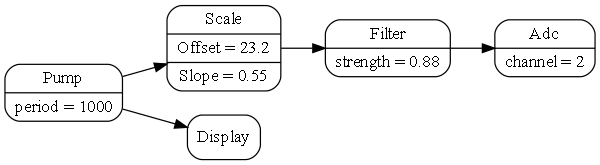
We’ve put the main loop into a new domain abstraction called Main. It pulls data from its request/response port and pushes it out on its output port at regular intervals. The execution model is working the same way as the conventional code.
The Main domain abstraction is not a great abstraction because it assumes all possible applications are just going to pump data.
Lets fix that:
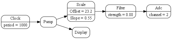
We have introduced a new domain abstraction called a 'Pump' that pulls data from a request/response port and then pushes it out of an output port. The pump has an input event port to tell it when to do it. Pump will also be a temporary abstraction, but lets run with it for now.
Note that the arrow between the clock and the pump is using the event programming paradigm. The arrows between the Pump, the Scale, the Filter and the Adc are the request/response programming paradigm. The arrow between Pump and Display is Dataflow (which pushes data).
Because the Adc takes real time, the pump, scaler, filter and ADC must all now have asynchronous request/response ports. So they must all be written in asynchronous style. But, if we look at the diagram, we can wonder if we really need to use request/response. Is it a left over artefact of the conventional code?
We can see that we can lose some of the request/response ports simply by moving the Pump.
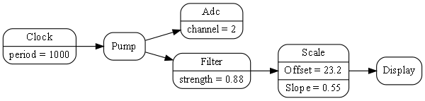
Now the Filter and Scale abstraction uses simple push ports.
Now let’s take this one step further. The Adc abstraction is more versatile if the event that starts it does not have to come from the same place where the output goes. In other words, the Adc would be a better abstraction if it had a pair of ports, an event input called start, and a push dataflow port called output.
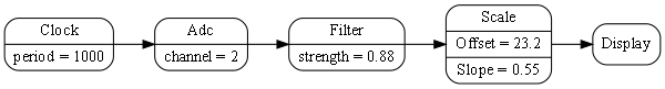
Now we don’t need the Pump. It was there just to make the request/response execution model work and wasn’t providing anything useful. The application just wires the clocked event source directly to the ADC.
Now we have exactly what we wanted when we wrote that earlier code that just composed ideas. The composition now seems natural and elegant. The idea of splitting a request/response port into two separate ports has actually lead to better abstractions and a better solution overall.
It also makes sense to split a request/response port when the requesting end is already a state machine. Waiting for the response becomes just another state, and the response becomes just another event wired back to the state machine machine.
For receiving the response, the requester has an input port and a function that implements the interface of that port. If that function makes a further request, the stack will have two returns pending, one for the original request and one for the 2nd request. Some systems use 'tail optimization' for this situation to stop the stack accumulating calls. Because request calls occur at the end of a function, tail optimisation converts the instruction from a call to a jump.
The request/response pattern is common so we prefer to implement it as a single port on each of the requester and responder with a single wiring.
In summary, all these techniques allow us to write asynchronous requesters, which allows us to avoid using multithreading.
However there is still danger associated with these asynchronous mechinams compared with synchronous function calls. The CPU is freed up to do other work while a request that takes real time is being processed. This is still concurrency, its just not fine grained concurrency that multithreading has. During concurrency, a shared state somewhere can be changed when you don’t expect it. For example, if the requester is performing a transaction such as the canonical debit one account and credit another, the requester that was written using normal synchronous calls is safe without locking the two accounts. This is because synchronous calls effectively lock everything by hogging the CPU resource until they complete. The asynchronous version has to be worried about what else might happen between two successive request/response calls. We call this type of non-splitable operation a transaction. Transactions still need explcit locking of resources that need to be kept in an internally consistent state. This needs to happen at the user story level becasue it is the user story that understands transactions. We can deal with this type of locking by using the "Arbitration programming paradigm", which is described later.
Multithreading
The conventional solution for function calls that take real time is to use multithreading.
At first this seems elegant as it keeps the same direct style syntax used for function calls that are non-blocking. This has the advantage that the code in the requester is written in almost the same way whether or not the instances it will be wired to will block. There is useful design-time decoupling resulting from that - the requester does not have to know what it will be wired to. It also appears to abstract concurrency, allowing other tasks to execute while the thread is blocked.
In ALA, every instance of an abstraction containing a prescriptive routine that could potentially block would need its own thread. But unfortunately threads do not remain confined within abstractions. They have far reaching effects as they call out into other abstractions. And abstractions that need to do work while waiting on a blocking call will themselves need multiple threads.
Because instances of abstractions do not know to whom they will be wired, they would need to assume that incoming function calls could be on a different thread. This would cause the multithreading model to have collaborative coupling between abstractions to have sufficient locking without causing deadlocks. This is the same problem for conventional classes as well, but its worse in ALA because abstraction internals must have zero design-time coupling with one another. They cannot collaborate on locking.
If a single thread is capable of doing all the work, I don’t recommend multithreading for solving the problem of function calls that take real time, even if unwieldy callbacks are the only alternative. Using callbacks to implement asynchronous ports is at least contained inside an abstraction.
Using non-preemptive multi-threading avoids race condition and deadlock problems by not requiring locks. All non-blocking sections of routines will run uninterrupted.
Once a multithreading is available, it tends to be the solution for every concurrency problem. That tends to commit code to prescriptive style even when a state machine would be better. (Prescriptive style as opposed to reactive style was discussed above.)
If we want to abort a blocked synchronous function call, (in the same way that we can abort an await with a CompletionToken,) we could have a second method in the programming paradigm interface called Cancel(). When the interface is implemented, the Cancel function (which has to run on a different thread) must release the block at the point where it is blocked, and cause it to return. It would return with a cancelled result so that the calling thread can follow a different flow. I have not tried this programming paradigm as yet.
Of course multithreading is still a solution for throughput types of performance issues. Multithreading is discussed further in a later section.
4.4.11. Priorities
Synchronous communications are deterministic. They prescribe the order in which everything happens. Furthermore, they effectively put a system wide lock on everything until the entire function calling tree completes. Nothing else can happen anywhere until it finishes.
Asynchronous communications, on the other hand, is inherently less deterministic. The non-determinism is made necessary by the external system, things like: real-time I/O, external networks, or by the need to improve performance.
During asynchronous communications, the functions can be executed in the order in which they are scheduled (using a simple queue) by default. This is what we did in the sample code at the start of this chapter. If this ordering scheme is used, then from the point of view of an asynchronous call tree, the natural order of execution is different from the synchronous function call tree. A synchronous function call tree will be depth first, whereas an asynchronous function call tree will be width first.
During the execution of a call tree, other call trees may be executing in parallel. This does not mean parallel in the fine grained sense of multithreading. It means parallel in the course grained sense that between the execution of asynchronous functions, other functions of other call trees may execute.
One consequence of asynchronous communications is that if any resource, including any object, is left in an invalid state between the running of two asynchronous functions, it must be locked. The need for locking is much less common than in a multithreaded situation. How locking can be accomplished without introducing coupling into the abstractions by using an arbitration programming paradigm is discussed later. Locking will change the order that functions execute.
The order of execution of asynchronous functions, can also be explicitly changed using priorities. Priorities are usually used to explicitly improve performance by doing more urgent things first.
Because the order of execution is outside the control of the abstractions involved, domain abstractions should not care about when it’s one-way asynchronous communications are executed. If the priority system were to reverse the order of execution of every asynchronous function in the system, a domain abstraction results should be the same (except for its performance). If the order does matter, the order needs to be explicit in some way. For example, a domain abstraction could use a 2-way communications port so that it gets a communication back when something is complete and it can move onto the next step. Another example is to use an activity programming paradigm (UML activity diagram). Abstractions have start input port and a finished output port. The application wires instances of them in a sequence.
Priorities are generally a system wide concern, so the application abstraction (or feature or user story abstractions) are the only ones that have the knowledge to know how to set priorities.
In conventional modular systems, priorities are usually a cross-cutting concern, but in ALA they are cohesive with the wiring code, which is already in one place for a given feature or user story. The application may need to. prioritize the features and user stories.
TBD Show example implementation code for priorities. Add an optional priority parameter to the WireTo of the asynchronous programming paradigm abstraction. The appplication can use priority numbers such as 0,1,2. We need a default priority so that WireTo can be called without specifying a priority. The application would configure the default, for example to 1.
The final requirement is that applications can still use the asynchronous programming paradigm without using priorities at all. There would be a default default priority level of 0.
A priority abstraction could be created in the domain abstractions layer. It would contain a dictionary for priority levels. You would not use an enum for priority level in this abstractions because the levels are specific to an application. The application configures the dictionary with level names such as Low, Middle, High, that associate with numeric priorities.
Also, we need to consider if domain abstractions may ever want to use priorities internally. If so we need to do it in such a way that they do not have a dependency on a priority abstraction because if they are used without priorities, we don’t want to have to include the priority abstraction.
4.4.12. Busy resources
When a resource that takes is used asynchronously, more than one user may try to use it at the same time. For example a transaction on a database may involve several asynchronous function calls, and have multiple users. It would need to be locked for the duration of the transaction. Or an ADC converter that takes time to do a conversion may be used by multiple users. It would be busy to new requests while it is performing a conversion. If the resource is busy, the communication to the resource will need to be queued until it is ready.
The reactor pattern can handle this situation. It can check if the receiver is busy before giving it the communication. The dispatcher wont remove asynchronous function calls from the queue unless the destination resource is ready for it.
If a simple event loop is used, a solution to this problem, is an intermediary object that is wired in front of the resource. It keeps its own queue of event objects. When the resource signals that it is free, it takes the first event from the queue and sends it to the resource via the main event loop. That way only one event at a time can be in the event loop’s queue.
4.5. Example Programming paradigms
In the previous section of this chapter, we discussed many aspects of execution models in general. Many were applicable to both event-driven and 1-way dataflow programming paradigms.
Nest we will look at some particular programming paradigms and see how their execution models might work. It is not an exhaustive list. There are no doubt many other possibilities waiting to be invented that have new meanings for the composition of abstractions, and allow succinct expression of requirements.
4.6. Request/response
A common type of 2-way communication is request/response. This programming paradigm is fundamentally an orchestration of two one-way messages, but we are used to thinking of it as a fundamental communication pattern in its own right. That’s because it’s implemented so easily with a common function call. Earlier in the chapter we observed that if requesters were asynchronous by nature, they would have wiring compatibility with either synchronous or asynchronous receivers. And we discussed ways of writing requesters to be asynchronous.
A request carries two types of implicit information. Firstly, since they are wired point to point, a request is implicitly a command. It doesn’t need any command name or any explicit data specifying a command. Secondly a request and a response implicitly carry timing information. The time that they occur is in itself information.
Examples of request/response:
-
The requester needs to know when it’s completed (before it continues with the next line of code).
-
The requester needs to know a success or failure status of a command.
-
The requester needs to request latest information (pull) (e.g. from an I/O port).
-
The requester needs to request lazy information (information not calculated until its needed).
-
The requester needs to request specific information e.g from a database.
4.6.1. Wiring incompatible request/response ports
As discussed in earlier sections, synchronous and asynchronous 2-way communications have different advantages. There is a principle, GALS, that suggests that we use synchronous locally (within a processor) and asynchronous globally across processors. I think this is too simplistic. There are reasons other than cross-processor communications that cause certain communications to take real time, such as IO or delays. These communications should be asynchronous, and then all the ones that might be wired to them need to be asynchronous as well. Nevertheless there may be some communications in the average application which needs the advantages of synchronous communications.
The request/response ports of domain abstractions may end up a mixture of synchronous and asynchronous.
If the requester is asynchronous and the responder is synchronous, there is little problem in connecting them using an intermediary object. When the requester calls the intermediary, the intermediary in turn calls the responder which returns immediately. The intermediary then places the result in the task or future object, or calls the requester back if it uses a callback.
If the requester is synchronous and the responder is asynchronous, it would be possible to create an intermediary adapter, but it will block the requester’s thread, which probably isn’t what we want. The requester would need its own thread (or its requester), which, as I said earlier I don’t recommend as the way to solve this problem. So they are essentially incompatible. The requester code would need to change to asynchronous, as described by one of the methods above.
4.7. Event-driven programming paradigm
We now return to the 'Event driven' programming paradigm. At the beginning of this chapter we showed both synchronous and asynchronous code examples of this paradigm, both of which used the IEvent interface.
'Event' is an overloaded term in software engineering. Sometimes it means asynchronous, as in using an event loop. Sometimes it means indirect, as in C# events. Sometimes it means both. Earlier in this chapter we clarified these two independent notions. We discussed that in ALA, communications between abstractions within a layer are always indirect and explicit. We also discussed that they may be either synchronous or asynchronous. And we discussed 1-way and 2-way communications.
The interpretation of event-driven that I use is asynchronous and 1-way. Of course it’s always indirect and explicit in ALA.
Note that this interpretation is different from the C# language version of events. C# events are synchronous (they get delivered and processed before the function returns). C# events also directly support fanout. C# receivers are usually registered by the receiver itself (observer or publish/subscribe pattern). In ALA of course, events must be wired by a layer above.
In my interpretation of the event-driven programming paradigm, output ports can only be wired point to point. You would use a fanout intermediary object to achieve wiring an event to multiple destinations.
Even though my interpretation of even-driven is asynchronous, the output ports use a function or method call. This is fine because they are 1-way communications. The function gets the event on its way and returns immediately. The return itself carries no information.
When an event is taken from the event queue and dispatched to the receiver, we call it a task. The task is just the execution of a function or method, (which is different from a C# task object). A task must always runs to completion quickly. No task should take real time to execute (spin loop, or block).
4.7.1. Events with parameters
Another section of this chapter discusses the dataflow programming paradigm. Dataflow can be similar to event-driven with a parameter when it pushes data. However Dataflow has variants where can be synchronous, can be pull rather than push, and can send a whole table of data in batches. For this reason Dataflow and event-driven are considered different programming paradigms.
4.7.2. Reactive vs prescriptive programming
Event-driven programming is a reactive style in that it contrasts with the prescriptive or orchestrated style of the imperative or activity programming paradigms. In event-driven, the system is idle until something happens, and then things react to it, possibly changing some state, possibly generating more events, completion events, or timeout events. Event driven systems like to use interrupt routines to get events from the outside into the system. The interrupt routine puts the event directly into the main loop event queue.
In a reactive system, we don’t know what will happen next, in either the outside world or what code will execute next. It is less deterministic. Reacting to an event often changes some stored state. This state may change the way we will react to subsequent events. In other words, event-driven often goes hand in hand with state machines.
Event-driven programming is generally not thought of as a request/response type of paradigm. There can be a response, but it would be thought of as a completely separate message that needs its own point to point wiring. We don’t need synchronous communications because there is no response associated with an event (in the same wiring).
ALA is polyglot with respect to programming paradigms, so there is no reason to try to make an entire system either event-driven or prescriptive. Both can be mixed for maximum expressibility of the requirements.
When there are no forces favouring reactive or prescriptive, I generally default to reactive. This is because reactive systems are more versatile in maintenance. A prescriptive style becomes awkward when an unforeseen event needs to be handled in the middle of a prescriptive routine. The flow of the routine becomes more complicated.
4.7.3. Properties of event-driven designs
-
Event-driven design easily accommodates events happening externally to the system at unpredictable times. We may be busy processing a previous event when a new events occurs. We typically have an interrupt put the event into the asynchronous event queue. When we are ready to process the event, we may still want to process higher priority events first.
-
Long running tasks such as a heavy algorithm or updating a large display may cause issues with latency for other events. They need to be split into a series of tasks, usually at the outer loop. The loop state needs to be coded manually as a state machine. The C# 'yield return' keyword will tell the compiler to do this for you.
-
Event driven systems need a Timer abstraction to be provided in the programming paradigms layer. The Timer can be asked to issue an event at a future time. It can be asked to issue events at regular intervals.
-
Wiring in ALA may be circular. There is no problem with this from a dependency point of view. Since event-driven is asynchronous there are no issues execution wise either. If they were synchronous, there would be recursion and an infinite loop. Events may flow around the circle continuously. If there are no delays around the circle, the main loop will be constantly busy processing the events as fast as it can.
Events in a loop should not fan out. Events in a loop that reproduce more events will overload the event queue.
-
The reactor pattern can be used for when the receiver is not ready. The reactor pattern is an event loop which will check if the receiver is in a ready state before dispatching any events to it.
-
A developer used to a synchronous function calling style may expect what looks like a synchronous function call inside a domain abstraction to fully process the event before returning. The port itself will show that it uses an IEvent interface. Inside the IEvent abstraction it can explain that it is an asynchronous programming paradigm. However, where the code actually sends the event, it will only have output.Send(); The choice of the word Send rather than Execute is to indicate it’s only sending the event not executing it.
-
Because the event-driven programming paradigm is asynchronous, senders and receivers can be on different processors or different locations. The decision about where instances of domain abstractions run can even be after the application or user stories abstractions are written. This means that within the architectural 4+1 views framework, the physical view can be changed independently of the logical view.
4.7.4. Global event names
Some conventional event-driven systems use global event names for inter-communication between modules. Each receiver names the events it is interested in, effectively a variation of the observer or publish subscribe pattern. They do this by registering to global event or signal names. This is considered relatively decoupled by its proponents, because senders and receivers don’t know directly about each other, only about global events names. It is illegal in ALA because most events will not abstract enough to be named and become globals. They will tend to be specific to pairs of modules that need to communicate.
Event names then essentially become symbolic wirings. Symbolic wiring is difficult to follow because you have to search for where the names appear throughout the entire code.
By effectively collaborating on symbol names, abstractions are coupled with each other still. It’s a rigid system because modules could not be rewired in a different way without changing them.
In ALA we use point to point wiring instead, or should I say port to port. Wiring is brought out to a coherent place. Because the wiring is point to point, the events are anonymous. You don’t have to name the lines on a diagram.
Having said that, it is possible to have an event that is abstract enough to go into a layer below. Such an event would need to be used by many many domain abstractions so that it is truly more abstract. If only a few domain abstractions need to use an event, then they should still use ports and be all wired up.
If you do create a global abstract event, it would be so ubiquitous that you never want to use the domain abstractions without it. They will have a dependency on it after all.
I can’t think of an example of such an event. Perhaps an event called initialize. It is generated after the wiring code has executed but before an application is set running. Domain abstractions use it to do initialization that needs the wiring in place.
Another example may be a closing event, giving domain abstraction instances a chance to persist their context data before the application closes down.
4.8. Dataflow
A dataflow model is a model in which wired instances in the program (or connected boxes on a diagram) are a path of data without being a path of execution-flow. The execution flow is like in another dimension relative to the data flow - it may go all over the place.
A stream of data flows between the connected components. Each component processes data at its inputs and sends it out of its outputs.
Each input and output can be operated in either push or pull mode. Usually the system prescribes all pull (LINQ), all push (RX), all inputs pull and outputs push (active objects with queues) or all outputs pull and inputs push (active connectors). In ALA we can use a mix of these different mechanism when we define the programming paradigm interfaces.
The network can be circular provided some kind of execution semantic finishes the underlying CPU execution at some point (see synchronous programming below).
The dataflow paradigm raises the question of type compatibility and type safety. Ideally the types used by the components are either parameterised and specified by the application at each connection or determined through type inference.
4.8.1. IDataFlow<T>
I frequently use dataflow execution models.
Here is one variation which works well:
TBD
This variation has these properties:
-
On a diagram, the line (wire) represents a variable that holds the value.
-
Fan-out - one output can connect to multiple inputs. All inputs read the same output variable.
-
Fan-in - multiple outputs cannot connect to one input.
-
Each output is implemented by a single memory variable whose scope is effectively all the places connected by the line (wire).
-
Receivers can get an event when the value changes
-
Receivers can read and re-read their inputs at any time.
-
Operator don’t need to have an output variable, they can pass the get through and recalculate every time instead.
Here is the version I use most often.
TBD
Note that domain abstractions may not collaborate on a specific type for T. A pair of domain abstraction may not, for example, share a DTO (data transfer object) class as that would then be an interface specific to one or other of those classes. T must be more abstract and come from a lower layer, so is often a primitive type from the programming language. T may be passed in by the application, which always knows types of data moving through the system.
Type inferencing is desirable. For example, an instance of a DataStore<T> abstraction could be configured by the application to have some specific fields. Ideally this is the only time the application specifies the fields. The application wires it to a select abstraction that removes one field and then to a join abstraction that adds one field. From there it is wired to a form abstraction that displays the fields. Ideally the form, select and join abstractions do not also have to be configured by the application to know the types of their ports. Instead they are able to infer the type as an anonymous class as it goes from port to port at compile-time.
4.8.2. ITable
This interface moves a whole table of data at once. The table has rows and columns. The columns are determined at runtime by the source.
Run-time types can also be used. For example, the fields in an instance of a table abstraction may not be fully known at compile-time. This is especially true if the table abstraction provides persistence, or, for example, if the data source is a CSV file with unknown fields. In this case a ITable programming paradigm would transfer type information at run-time as well as the data itself.
TBD implementation examples
4.8.3. Glitches
All systems can have glitches when data flows are pushed in a diamond pattern. The diamond pattern occurs when an output is wired to two or more places, and then the outputs of those places eventually come back together. If they never come together, even both seen by a human, then we generally don’t care what order everything is executed in. But when they come together, the first input that arrives with new data will cause processing, and use old data on the other inputs. This unplanned combination of potentially inconsistent data processed together is a glitch. It even happens in electronic circuits.
The following composition of dataflow operators is meant to calculate (X+1)*(X+2)

When X changes, there can be a glitch, a short period of time, in which the output is (Cnew+1)*(Cold+2).
In imperative programming, this problem is up to the developer to manage. He will usually arrange the order of execution and arrange for a single function or method to be called at the place where the data-paths come back together. As he does this, he is introducing a lot of non-obvious coupling indisde the modules of the system, which is one of the big problems with imperative programming.
When we have composability, we don’t know inside the abstractions how data will propagate outside, and how it will arrive at its inputs. We want to execute whenever any of our inputs change, because as far as we know it may be the only change that might happen. So we really want the execution model to take care of eliminating glitches automatically for us.
This is a work in progress for the IDataFlow execution model described above. In the meantime, as a work-around I take care of it at the application level using a pattern. When I know dataflows will re-merge in a potentially inconsistent manner, I wire in an instance of an abstraction called 'Order' between the output and all its destination inputs. This instance of order is configured to explicitly control the order that the output date stream events are executed in. Then I will use a second abstraction called 'EventBlock' at the end of all data paths except one, the one that executes last.
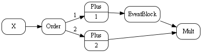
By default multiple IDataFlows wired to a single output are executed in the order that they are wired anyway. On the diagram, they are drawn top to bottom in that order. This improves the determinism but is a little too implicit for my liking, so that is why I use the order abstraction.
4.8.4. Live dataflow
As used in the coffee-maker example earlier, this paradigm simulates electronic circuits instead of using the concept of discrete messages. Semantically the inputs have the values of the outputs they are wired to at all times. This type of flow is readily implemented with shared memory variables.
FRP (Functional Reactive Programming) also is effectively a live dataflow execution model.
4.8.5. Synchronous dataflow
The use of the word synchronous here is different from its use in the discussion of synchronous/asynchronous events above. Here it means a master system clock clocks the data around the system on regular ticks. At each tick, every instance latches its own inputs and then processes them and places the results on their outputs. Data progresses through one operator per tick, so takes more time to get through the system from inputs to outputs. The result is a more deterministic and mathematically analysable system.
The execution timing and the timing of outputs occurs at a predictable tick time, albeit on a slower time scale than an asynchronous system. All timings are lifted into the normal design space.
Glitches that could occur in an asynchronous system (discussed earlier) are eliminated at the level of single clock ticks. A fast glitch could not occur. A glitch would occur when different data paths had different lengths, and would last for at least one tick duration. Controlling glitches is therefore lifted into the normal design space.
4.9. Activity-flow
The name Activity-flow comes from the UML activity diagram. Activities that are wired together execute in order. One starts when the previous one finishes. The activity itself may take a long time to complete (without blocking the CPU). Activity flows can split, run concurrently and recombine.
Activity-flow contrasts with event-driven. Where event-driven is reactive, activity-flow is prescriptive. It orchestrates what will happen rather than reacting to what might happen.
Activity-flow is not the same as the old flow diagrams. Flow diagrams were for the imperative programming paradigm where the flow was the flow of the CPU. Activity flow can have delays and other time discontinuities as it syncs with what’s happening in the outside world.
Activity-flow’s execution model can be the same as event driven. Each domain abstraction has a start input port and a done output port. The 'done' port of one instance of a domain abstraction can be wired to the 'start' port of the next. The ports are just event ports and can be wired for synchronous or asynchronous execution.
If the Activity-flow is a linear sequence, we can consider wiring the instances using text. However activity-flow abstractions will often need other wiring (using other programming paradigms) to UI or other input/output. C The domain abstractions may have request/response ports for their I/O. These may be synchronous or asynchronous depending on the design factors discussed earlier. It may wish to poll something external at regular intervals to see if it’s complete, so it may register on a timer for regular events. (The timer is an abstraction in the programming paradigms layer, which is typically wired to the event-loop abstraction for asynchronous execution).
The domain abstractions may internally use an asynchronous execution model, such as for a delay.
4.9.1. Structured activity flow wiring using text (experimental)
This is a thought experiment at this stage. The experiment is to see if we can do structured programming for activity flow. Remember activity flow is instances of domain abstractions, each of which generally has a start port and a done port.
The idea is to mimic imperative structured programming. Structural programming is what got rid of the goto and introduce block structured statements such as while and if. It is generally laid out with indenting that exactly matches the nested structure of braces. Your brain sees the indenting but the compiler sees the curly braces. (Except for Python which makes the compiler use what the brain sees).
In this program, we will string together some instances of domain abstractions and include a loop and a conditional. The indenting structure is the same as for the imperative version.
Remember this code is not executing the activity flow, it is just wiring it all up for later execution.
TBD need the corrsponding diagram here to show what this code is trying to do
program = new A();
    program.
    .WireIn(new B())
    .WireIn(
        Loop (
            new C()
            .WireIn(
                If (new D(),
                    new E(),
                    new F()
                )
            )
            .WireIn(new G())
            ,
            new H();
        )
    )
    .WireIn(new I())
First remember that WireIn returns its second parameter to support this fluent style. A is the first activity. A’s done port is wired to B’s start port, so B is the second activity. Everything else is in a loop. The 'Loop' function takes two parameters, one is another flow and one is the looping condition, which in this case is H. B gets wired to C. 'If' is a function that takes three parameters, a condition, which in this case is D, and two flows. C gets wired to D. The 'If' function expects D to have two done ports, called donetrue and donefalse. It wires donetrue to E. It wires donefalse to F. 'If' wires the done ports of both E and F to a null activity instance to recombine the flow. The null instance is returned by 'If'. The null instance is wired to G. G gets wired to H. The 'Loop' function expects H to have two exit ports calls done and loop. 'Loop' wires H’s loop port to C, and returns H. H is wired to I.
This code looks okay, however, as is often the problem with text based representations of relationships, most of the instances will probably need additional wiring to other things as well. If this is the case, and the requirements implicitly contains a graph structure rather than a tree structure, then a diagram wll be the best way to represent it.
4.10. Work-flow
Persisted Activity-flow. This includes long running activities within a business process such as an insurance claim.
4.11. IIterator
This dataflow interface allows moving a finite number of data values at once. It does so without having to save all the values anywhere in the stream, so has an efficient execution model that moves one data value at a time through the whole network.
This is the ALA equivalent of both IEnumerator and IObserver as used by monads. ALA uses the WireTo extension method that it already has to do the Bind operation. So the IIterator interface is wired in the same consistent way as all the other paradigm interfaces. There is no need for IEnumerable and IObservable type interfaces to support Also unlike monads, multiple arbirary interfaces can be wired between two objects with a single wiring operation.
IIterator has two variants that handle push and pull execution models. Either the A object can push data to the B object, or the A object can pull data from the B object.
TBD implementation examples
4.12. UI layout
This programming paradigm is used for laying out a graphical user interface. A relationship means put the target instance of a UI element inside the first instance of a UI element. The order of the fanout of relationships sets the order that the elements appear. For most UI domain abstractions, UI elements default to going go vertically downwards.
I use two domain abstractions called vertical and horizontal to control whether they are layed out vertically or horizontally.
Here is the interface for use by domain abstractions that will use .NET’s WPF class library for the implementation.
using System.Windows;

namespace ProgrammingParadigms
{
    /// <summary>
    /// Hierarchical containment structure of the UI
    /// </summary>
    public interface IUI
    {
        UIElement GetWPFElement();
    }
}
This programming paradigm is similar to XAML. It doesn’t use XML syntax, it uses wiring code or diagrams the same as all other programming paradigms. Binding to data in XAML is done using dataflow ports on domain abstractions. Unlike XML, the entire application is built the same way.
4.15. Locking resources
Even in a single threaded system, we still have concurrency at a course grained level. We want to allow our one thread to do other tasks whenever something else is waiting. Or, whenever an asynchronous communication occurs, we may choose to do previously queued tasks, or higher priority tasks, before processing the latest one. We can call the concurrent sets of tasks an activity.
We may have a resource or external device that can be be used by multiple activities. There is a set of tasks that need to complete on the resource without interrupton by other activities. This is called a transaction. Examples of resources that can have transactions are a database or an external device such as a robot arm. Several queries or movements may be involved in the transaction.
We need a locking mechanism for the resource. I recommend an arbitration programming paradigm. At the application level, we need to specify which instances of domain abstractions that perform transactions need to collaborate by locking or waiting for a given resource.
Every domain abstractions that performs a transaction on a given resource has a port of this programming paradigm. All instances using a given resource are wired to a single instance of an arbitrator abstraction. Effectively this wiring specifies the collaboration that must occur between the instances. This collaboration is done at the abstraction level of the system, where it belongs, not inside the abstractions.
The ALAExample project at www.github.com/johnspray74 has an example of this. The IArbitrator interface is considered a programming paradigm. It contains an async method for locking the resource. This method can be awaited on until the resource is free. A second method releases the resource, which would allow another activity waiting to proceed.
The arbitrator abstraction could be given the ability to detect deadlocks and even break deadlocks.
4.16. State machines
To get used to how different these programming paradigms can be, let’s go now to something completely different - state machines. We wont be going into understanding them at the code level because we want to support hierarchical state machines, and the code for that is a little bit non-trivial, but we do want to get an understanding of how state machines are just another programming paradigm that allows us to wire together instance of abstractions. The meaning of the wiring is different than what it was for the event programming paradigm.
I assume a basic understanding of what state machines are.

At first it can be difficult to express the solution to a requirements problem as a state machine, even when the state machine is a suitable way to solve the problem. It takes some getting used to the first time. But it only takes a little bit of practice to begin to master it.
I once had to express a set of user stories that involved different things that could happen from the outside, either through the UI or other inputs. I knew these were the kind of user stories that were nicely expressed by a state machine, but I had no idea where to start. I only knew that the previously written C code to do the job was a big mess that could no longer be maintained. But I started drawing the state machine, first on paper and then in Visio, and everything started to fall into place very nicely. Before I knew it I had represented what used to be 5000 lines of C code by a single A3 sized state machine diagram. This diagram so well represented the user stories that it was easy to maintain for years to come. This experience was a big factor in the final conception of ALA.
Here is the diagram.
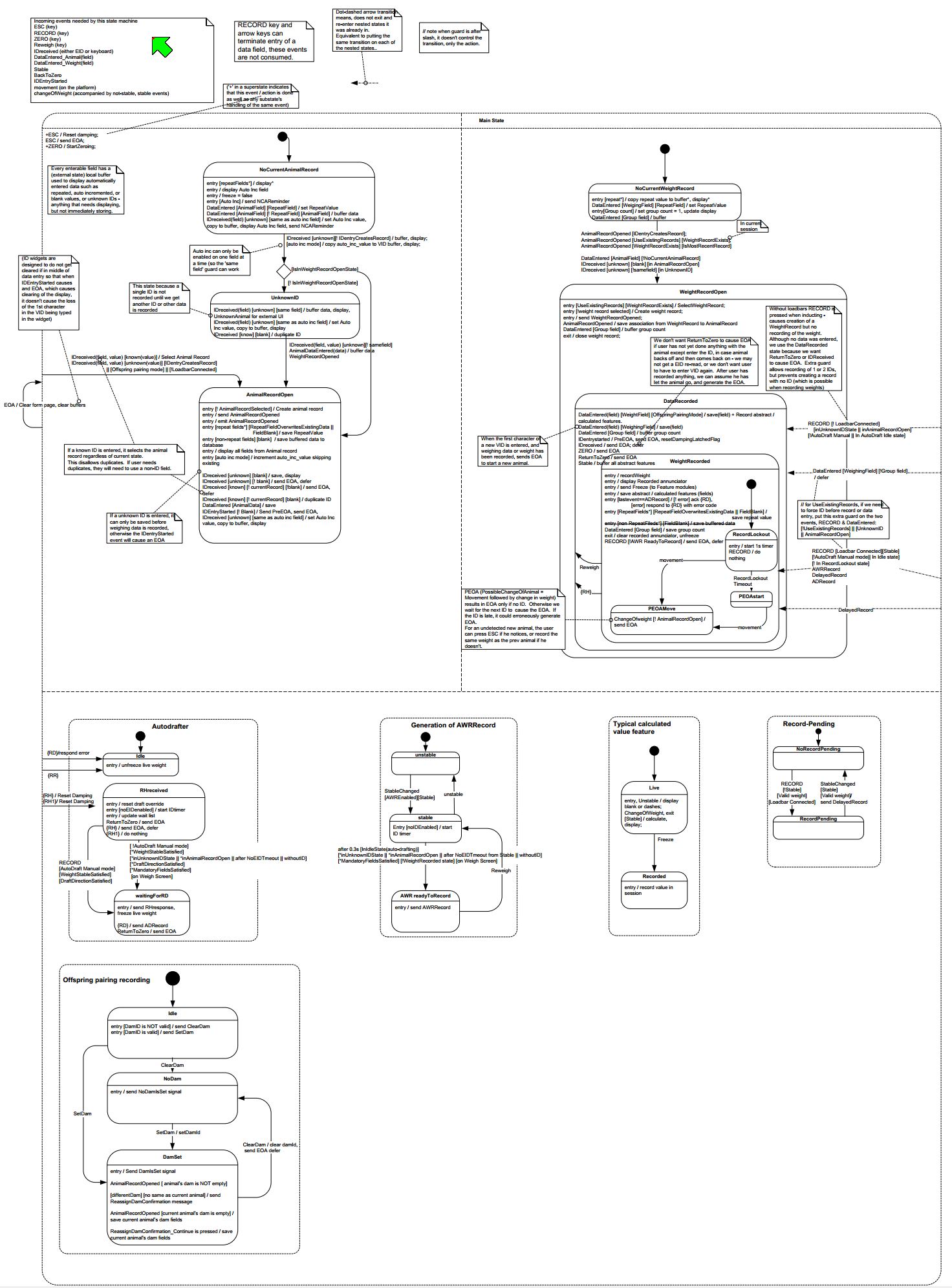
Notice that the diagram makes heavy use of hierarchical states (boxes inside boxes). These turn out to be important in most of my state machines.
State machine diagrams are drawn in their own unique way. The boxes of the diagram are instances of the abstraction "State". The lines on a state machine diagram are actually instances of another abstraction, "Transition". Out of interest, to relate a state machine diagram to a more conventional ALA wiring diagram, you would replace all the lines on the state machine with boxes representing instances of Transition. The event, guard and actions that associate with a transition then go inside the transition box to configure it. Lines would then wire the transition box to its source state instance and destination state instance. Hierarchy is drawn on the state machine by boxes inside boxes, but in the conventional ALA wiring diagram, the boxes would be drawn outside with lines showing the tree structure. This analogous to the tree structured wiring we have used in previous examples for expressing UIs, which are actually 'contains' relationships.
The graphical tool being developed will allow the drawing of hierarchical state machines. It will internally transform it to conventional wiring of instances of states and transitions. Interfaces called something like ITransitionSource, ITransitionDestination and IHiercharical would be used to make it execute. It is a simple matter to write code inside the state and transition abstractions to make them execute that would be adequately efficient for most purposes.
How to make hierarchical state machine execute in an optimally efficient way is a non-trivial problem, but I have worked out the templates for what the C code should look like. Generating this code is a topic for another web page.
4.17. Imperative
Much conventional code is written using the so called imperative programming paradigm. This paradigm has the same execution model of the underlying CPU hardware. Imperative means sequential execution flow of instructions or statements in computer time.
Imperative is seldom a good programming paradigm for expressing whole user stories. Even though we call our imperative languages high level languages, its actually quite a low level programming paradigm. However it is efficient because it executes almost directly on the hardware. Imperative highly prescriptive. We can code applications in it directly or we can use it to build other programming paradigms.
Function or method calls go to a named destination, and are synchronous (pass the CPU to the called function for execution, and pass it back to the caller on completion.
The imperative programming paradigm is wonderful for writing algorithms that are not tied to real-time. However, in modern software, that is a tiny fraction of what programs do. We will seldom use the 'imperative' programming paradigm in ALA.
Imperative can be structured to comply with ALA constraints, almost. The user story simply makes function calls or method calls to the domain abstractions in the layer below. The problem is that the user story ends up controlling the execution flow, and it handles the data at runtime. The data it receives from one domain abstraction will be passed to the next domain abstraction. This is not really a responsibility we want to put on the user story. We want to factor out execution flow and data. We want the user story to be just about composing instances of domain abstractions.
4.18. Multithreading
Compared with ALA, modular programming will look like a big pool of mud. Multithreaded programming will look like a big pool of boiling mud.
In the section about request/response, we briefly considered using multithreading to solve the problem when the request/response is implemented as a synchronous function call, but it takes time and the call blocks.
In this section we discuss briefly why we avoid using multithreading to solve that particular problem, and discuss what problems might justify using multithreading.
TBD WIP
Because threads block, we must put everything that needs to be concurrent on different threads. Whether it’s a conventional architecture or an ALA architecture this leads to coupling throughout the system. Modules may tend to be based on threads rather than a more logical separation. Furthermore, different parts of the system have to collaborate by locking accesses to shared state. There is a misconception that shared state is caused by globals. This is incorrect. Shared state occurs all the time in object oriented programs. Any objects accessed from different threads are shared state even if all state in an object is private. So if a UI object gets work done by a different thread so that the UI remain responsive, then the result will come back to the UI objects on a different thread unless this is carefully avoided. By default most objects are not thread-safe. Missing locks will lead to race conditions. As locks are added, there is even more blocking occurring. This can reduce performance, increase non-determinism, or require even more threads. Too much locking can lead to deadlocks or priority inversions. These issues will hide and appear rarely.
Unless it is required for latency or other performance throughput reasons that can’t be solved on a single thread, I don’t recommend going into the quagmire of pre-emptive multithreading. Even if another thread is needed for a specific performance case, I still recommend putting the majority of code in one thread despite any difficulties that entails (as discussed below).
4.19. Agent based programming
Note that there is a different programming style of multithreading that doesn’t use shared state. It is called agent based programming. In this style, we think of every thread as effectively being on a different processor. They can only communicate with one another with messages. Every thread has a single input queue. All communications are asynchronous. Synchronous calls between agents is not possible, so there is no shared state.
The thread’s main loop does nothing other than take events from the input queue one at a time, process them, and asynchronously sends events to other such threads. This execution model is a completely different thing. It is called the agent model or producer/consumer. It is safe because there is no shared state and locks are not required. If there is a 'shared' resource, one thread can be assigned to resource. This model does not solve the problem of how to do synchronous request-response calls that block. It is not even the prescriptive programming style that we are trying to achieve with request/response. Every thread is already transformed into a reactive style. Such an execution model is equivalent to a single threaded system where all calls are asynchronous. Like an all asynchronous execution model, performance can be improved by assigning certain abstraction instances to their own processors.
4.19.1. State machine vs multithreading concurrency styles
A bigger problem with callback functions or futures is that if the requester call is inside structured statements such as a loop or if statement, or has been called from another function, all the code right back to main() needs to be rewritten like a state machine. It must keep state variables to remember what would normally be implicit in the program counter state, and manually store any other stack based state that the compiler would normally handle for the execution flow through the program. If the code is a simple function called directly from main, this can be done fairly easily. Each time the function is called, it reads the state, which is usually a function pointer, and dispatches to it. Callbacks or continuations go to their own functions.
+ An advantage of this style of programming is that it easily handles all time discontinuities - things that would otherwise block a thread. It allows reacting to unexpected events much more easily. And it allows longish routines to yield by simply returning part way through, say inside a loop, to reduce the latency of any other concurrent tasks waiting to execute. When the main loop calls back, it can use the state variables to resume processing where it left off.
+ The great disadvantage of this style of programming is when the program is more prescriptive than reactive. There is a fixed sequence of things that will happen, and we want to express that as normal sequential lines of code, even though certain operations will block. For example, we are moving a large amount of data. Exceptions to the prescribed sequence are rare. I find that async/await or co-routines are the best solutions for this situation. If they are not available, then a cooperative (non-preemptive) thread could be considered to solve the one situation.
+ One of the most common requirements for concurrency is responding to user input. For this we may specify a soft deadline of 0.1s. This means that all state machine, callbacks, or other run-to-completion routines should execute in less than 0.1s. This not difficult to do because the vast majority will execute very quickly. What I sometimes do is put in a system timer to measure the longest running routine. It’s usually updating a large display.
+ What I see happening in most traditional systems is that once an RTOS is included in the system, it is considered to be the solution to all concurrency in the system. But probably 99% of concurrency in most systems can be done on a single thread. Most tasks may have priorities, but will wait until the CPU resource gets to them. So what I do is avoid using threads except for when the specific case of performance can’t be solved in any other way. So, in my entire career in embedded systems, I have never ended up having to use a second thread, even when I have an RTOS already in the system at my disposal. Short interrupt routines have handled all situations with hard real time latency requirements. The state machine programming style has better suited the reactive nature of most embedded systems.
+ Remember you can only have one highest priority thread. If you are really in a situation where you have one or more hard real time deadlines that can’t be done in interrupts, then you should probably consider putting in multiple MCUs rather than trying to do, for example, rate-monotonic analysis.
+ Of course, if your system has multiple CPU cores, then you probably have a performance requirement that will need multiple threads to make use of them.
|
Some people, when confronted with a problem, think "I know, I’ll use regular expressions." Now they have two problems. - Jaimie Zawinski Some people, when confronted with a problem, think "I know, I’ll use threads." Now they have ten problems. - Bill Schindler |
4.20. Example project - Ten-pin bowling
The full source code for the bowling application can be viewed or downloaded from here: https://github.com/johnspray74/GameScoring
The ten-pin bowling problem is a common coding kata. Usually the problem presented is just to return the total score, but in this example we will tackle the more complicated problem of keeping the score required for a real scorecard, which means we need to keep all the individual frame ball scores. We can afford to do this even for a pedagogical sized example because ALA can provide a simple enough solution.
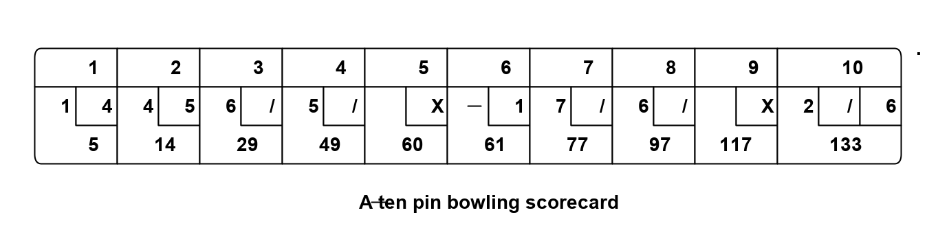
The ALA method starts by "describing the requirements in terms of abstractions that you invent". When we start describing the requirements of ten-pin bowling, we immediately find that "a game consists of multiple frames", and a "frame consists of multiple balls". Let’s invent an abstraction to express that. Let’s call it a "Frame". Instances of Frame can be wired together by a "ConsistsOf" relationship. So let’s invent an abstract interface to represent that, and call it 'IConsistsOf'.
Here is the diagram of what we have so far.
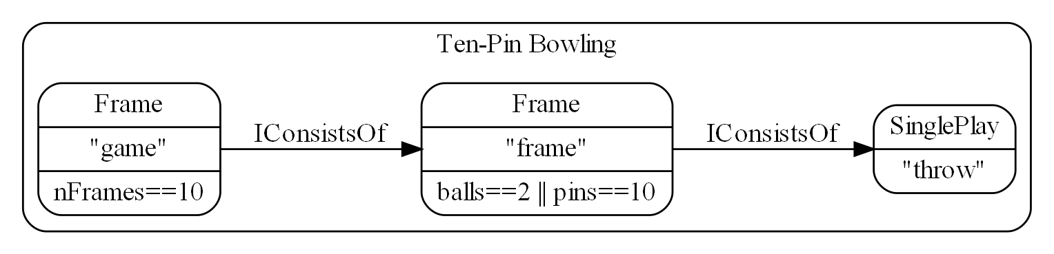
This is the first time we are using a diagram for an ALA application, so le’s go through the conventions used.
The name in the top of the boxes is the abstraction name. The name just beneath that is the name of an instance of the abstraction. For the bowling application above, we are using two instances of the Frame abstraction, one called "game" and one called "frame". Below the abstraction name and instance name go any configuration information of the instance.
The Frame abstraction is configured with a lambda function to tell it when it is finished. The Frame abstraction works like this - when its last child is complete it will create a new one. It will stop doing that when the lambda expression is true. It will tell its parent it is complete when both the lambda expression is true and its last child Frame is complete.
The end of the chain is terminated with a leaf abstraction that also implements the 'IConsistsof' interface called 'SinglePlay'. It represents the most indivisible play of a game, which in bowling is one throw. Its job is to record the number of pins downed.
The concept in the Frame abstraction is that at run-time it will form a composite pattern. As each down-stream child frame completes, a Frame will copy it to start a new one. This will form a tree structure. The "game" instance will end up with 10 "frames", and each frame instance will end up with 1, 2 or 3 SinglePlays.
Note, in reference to the ALA layers, this diagram sits entirely in the top layer, the Application layer. The boxes are instances of abstractions that come from the second layer, the Domain Abstractions layer. The arrows are instances of the programming paradigm, 'InConsistsOf', which comes from the third layer, the ProgrammingParadigms layer.
This diagram will score 10 frames of ten-pin bowling but does not yet handle strikes and spares. So let’s do some 'maintenance' of our application. Because the application so far consists of simple abstractions, which are inherently stable, maintenance should be possible without changing these abstractions.
The way a ten-pin bowling scorecard works, bonuses are scored in a different way for the first 9 frames than for the last frame. In the first nine frames, the bonus ball scores come from following frames, and just appear added to the frame’s total. They do no appear as explicit throws. In the last frame, they are shown as explicit throws on the scorecard. That is why there are up to 3 throws in that last frame.
To handle the different last frame, we just need to modify the completion lambda expression to this.
frameNum<9 && (balls==2 || pins==10) // completion condition for frames 1..9
|| (balls==2 && pins<10 || balls==3) // completion condition for frame 10
To handle bonuses for the first 9 frames, we introduce a new abstraction. Let’s call it Bonuses. Although we are inventing it first for the game of ten-pin bowling, it is important to think of it as a general purpose, potentially reusable abstraction.
What the Bonus abstraction does is, after its child frame completes, it continues adding plays to the score until its own lambda function returns true.
The completed ten-pin bowling scorer is this:
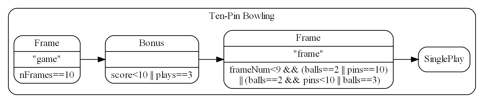
Note that the "game" instance (the left box of the diagram) implements IConsistsOf. This is where the outside world interfaces to this scoring engine. During a game, the number of pins knocked down by each throw is sent to this IConsistsOf interface. To get the score out, we would call a GetScore method in this interface. The hard architectural work is done. We have invented abstractions to make it easy to express requirements. We have a diagram that describes the requirements. And the diagram is executable. All we have to do is put some implementation code inside those abstractions and the application will actually execute.
First let’s turn the diagram into equivalent code. At the moment, there are no automated tools for converting such diagrams to code. But it is a simple matter to do it manually. We get the code below:
private IConsistsOf game = new Frame("game")
    .setIsFrameCompleteLambda((gameNumber, frames, score) => frames==10)
    .WireTo(new Bonus("bonus")
        .setIsBonusesCompleteLambda((plays, score) => score<10 || plays==3)
        .WireTo(new Frame("frame")
            .setIsFrameCompleteLambda((frameNumber, balls, pins) => frameNumber<9 && (balls==2 || pins[0]==10) || (balls==2 && pins[0]<10 || balls == 3))
            .WireTo(new SinglePlay("SinglePlay")
    )));
All we have done is use the 'new' keyword for every box in the diagram. We have made the constructor take the instance name as a string. (This name is not used except to identify instances during debugging.) We use a method called "WireTo" for every line in the diagram. More on that in a minute. And we pass any optional configuration into the instances using setter methods. The WireTo method and the configuration setter methods all return the 'this' pointer, which allows us to write this code in fluent style. If you are not familiar with fluent style it is just making methods return the this reference, or another object, so that you can chain together method calls using dot operators.
Not all ALA applications will be put together using the method in the previous paragraph, but I have found it a fairly good way to do it for most of them, so we will see this same method used for other example projects to come.
So far, this has been a fairly top-down, waterfall-like approach. We have something that describes all the details of the requirements, but we haven’t considered implementation at all. Past experience tells us this may lead us into dangerous territory. Will the devil be in the details? Will the design have to change once we start implementing the abstractions? The first few times I did this, I was unsure. I was not even sure it could actually be made to work. The reason it does work is because of the way we have handled details. Firstly all details from requirements are in the diagram. The diagram is not an overview of the structure. It is the actual application. All other details, implementation details, are inside abstractions, where they are hidden even at design-time. Being inside abstractions isolates them from affecting anything else. So, it should now be a simple matter of writing classes for those three abstractions and the whole thing will come to life. Implementing the three abstractions turns out to be straightforward.
First, design some methods for the IConsistOf interface that we think we will need to make the execution model work:
    public interface IConsistsOf
    {
        void Ball(int score);
        bool IsComplete();
        int GetScore();
        int GetnPlays();
        IConsistsOf GetCopy(int frameNumber);
        List<IConsistsOf> GetSubFrames();
    }
The first four methods are fairly obvious. The Ball method receives the score on a play. The Complete, GetScore and GetnPlays methods return the state of the sub-part of the game. The GetCopy method asks the object to return a copy of itself (prototype pattern). When a child frame completes, we will call this to get another one. The GetSubFrames method is there to allow getting the scores from all the individual parts of the game as required.
The SinglePlay and Bonus abstractions are very straightforward.
So let’s code the Frame abstraction. Firstly, Frame both implements and accepts IConsistsOf. A field is needed to accept an IConsistsOf. The WireTo method will set this field:
// Frame.cs
private IConsistsOf downstream;
Frame has one 'state' variable which is the list of subframes. This is the composite pattern we referred to earlier, and what ends up forming the tree.
// Frame.cs

private List<IConsistsOf> subFrames;
private readonly Func<int, int, int, bool> isFrameComplete;
private readonly int frameNumber = 0;
The second variable is the lambda expression that is a configuration passed to us by the application. It would be readonly (immutable) except that I wanted to use a setter method to pass it in, not the constructor, to indicate it is optional.
The third variable is the frameNumber, also immutable. It allows frame objects to know which child they are to their parent - e.g. 1st frame, 2nd frame etc. This value is passed to the lambda expression in case it wants to use it. For example, the lambda expression for a bowling frame needs to know if it is the last frame.
The methods of the IConsistsOf interface are now straightforward to write. Let’s go over a few of them to get the idea. Here is the most complicated of them, the Ball method:
public void Ball(int player, int score)
{
    // 1. Check if our frame is complete, and do nothing
    // 2. See if our last subframe is complete, if so, start a new subframe
    // 3. Pass the ball score to all subframes

    if (IsComplete()) return;

    if (subFrames.Count==0 || subFrames.Last().IsComplete())
    {
        subFrames.Add(downstream.GetCopy(subFrames.Count));
    }

    foreach (IConsistsOf s in subFrames)
    {
        s.Ball(player, score);
    }
}
It looks to see if the last child frame has completed, and if so starts a new child frame. Then it just passes on the ball score to all the child objects. Any that have completed will ignore it.
The IsComplete method checks two things: 1) that the last child object is complete and 2) that the lambda expression says we are complete:
private bool IsComplete()
{
    if (subFrames.Count == 0) return false; // no plays yet
    return (subFrames.Last().IsComplete()) &&
        (isLambdaComplete == null ||
         isLambdaComplete(frameNumber, GetnPlays(), GetScore()));
}
GetScore simply gets the sum of the scores of all the child objects:
private int GetScore()
{
    return subFrames.Select(sf => sf.GetScore()).Sum();
}
The GetCopy method must make a copy of ourself. This is where the prototype pattern is used. This involves making a copy of our child as well. We will be given a new frameNumber by our parent.
IConsistsOf GetCopy(int frameNumber)
{
    var gf = new Frame(frameNumber);
    gf.objectName = this.objectName;
    gf.subFrames = new List<IConsistsOf>();
    gf.downstream = downstream.GetCopy(0);
    gf.isLambdaComplete = this.isLambdaComplete;
    return gf as IConsistsOf;
}
The few remaining methods of the IConsistOf interface are trivial. The implementation of IConsistsOf for the other two abstractions, SinglePlay and Bonuses, is similarly straightforward. Note that whereas Frame uses the composite pattern, Bonuses uses the decorator pattern. It implements and requires the IConsistsOf interface. The SinglePlay abstraction, being a leaf abstraction, only implements the IConsistsOf interface.
One method we haven’t discussed is the wireTo method that we used extensively in the application code to wire together instances of our domain abstractions. The wireTo method for Frame is shown below:
public Frame WireTo(IConsistsOf c)
{
    downstream = c;
    return this;
}
This method does not need to be implemented in every domain abstraction. I use an extension method for WireTo. The WireTo extension method uses reflection to find the local variable to assign to.
The WireTo method will turn out to be useful in many ALA designs. Remember in ALA we "express requirements by composing instances of abstractions". If the 'instances' of 'abstractions' are implemented as 'objects' of 'classes', then we will use the wireTo method. If the 'instances' of 'abstractions' are 'invocations' of 'functions', as we did in the example project in Chapter One, we wont use WireTo obviously. In the coffeemaker example to come, 'instances' of 'abstractions' are 'references' to 'modules' because a given application would only have one of each abstraction.
The wireTo method returns 'this', which is what allows the fluent coding style used in the application code. The configuration setter methods also return the this reference so that they too can be used in the fluent style.
Here is the full code for the Frame abstraction (with comments removed as we just explained everything above):
// Frame.c
using System;
using System.Collections.Generic;
using System.Linq;
using GameScoring.ProgrammingParadigms;
using System.Text;

namespace GameScoring.DomainAbstractions
{

    public class Frame : IConsistsOf
    {
        private Func<int, int, int[], bool> isLambdaComplete;
        private readonly int frameNumber = 0;
        private IConsistsOf downstream;
        private string objectName;
        private List<IConsistsOf> subFrames = new List<IConsistsOf>();


        public Frame(string name)
        {
            objectName = name;
        }


        public Frame(int frameNumber)
        {
            this.frameNumber = frameNumber;
        }


        // Configuration setters follow.

        public Frame setIsFrameCompleteLambda(Func<int, int, int[], bool> lambda)
        {
            isLambdaComplete = lambda;
            return this;
        }


        // Methods to implement the IConsistsOf interface follow


        public void Ball(int player, int score)
        {
            if (IsComplete()) return;

            if (subFrames.Count==0 || subFrames.Last().IsComplete())
            {
                subFrames.Add(downstream.GetCopy(subFrames.Count));
            }

            foreach (IConsistsOf s in subFrames)
            {
                s.Ball(player, score);
            }
        }


        public bool IsComplete()
        {
            if (subFrames.Count == 0) return false;
            return (subFrames.Last().IsComplete()) &&
                (isLambdaComplete == null ||
                 isLambdaComplete(frameNumber, GetnPlays(), GetScore()));
        }


        public int GetnPlays()
        {
            return subFrames.Count();
        }


        public int[] GetScore()
        {
            return subFrames.Select(sf => sf.GetScore()).Sum();
        }


        List<IConsistsOf> IConsistsOf.GetSubFrames()
        {
            return subFrames;
        }


        IConsistsOf IConsistsOf.GetCopy(int frameNumber)
        {
            var gf = new Frame(frameNumber);
            gf.objectName = this.objectName;
            gf.subFrames = new List<IConsistsOf>();
            gf.downstream = downstream.GetCopy(0);
            gf.isLambdaComplete = this.isLambdaComplete;
            return gf as IConsistsOf;
        }

    }
}
4.21. Example project - Tennis
Now let’s modify the bowling application to score tennis. If the bowling game hadn’t been implemented using ALA, you probably wouldn’t contemplate doing this. But ALA excels for maintainability, and I want to show that off by changing Bowling to Tennis. The Frame and IConsistsOf abstractions look like they could be pretty handy for Tennis. A match consists of sets, which consists of games, which consists of SinglePlays.
We will need to make a small generalization to the Frame abstraction first. This will allow it to keep score for two players. We just change the type of the score from int to int[]. The Ball method will be generalised to take a player parameter to indicate which player won a play. A generalization of an abstraction to make it more reusable is a common operation in ALA.
The only other thing we will need to do is invent a new abstraction to convert a score such as 6,4 into a score like 1,0, because, for example, the winner of a game takes one point into the set score. This new abstraction is called WinnerTakesPoint (WTP in the diagram).
Here is the tennis scoring game:
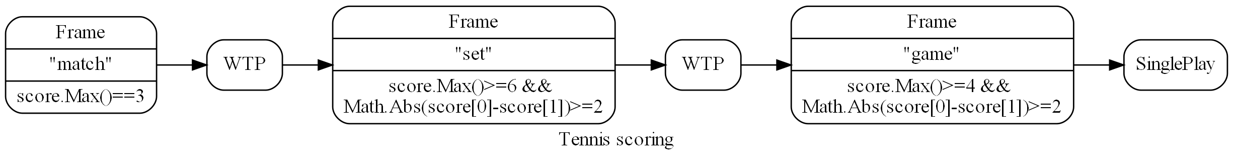
The diagram expresses all the details of the requirements of tennis except the tiebreak.
Here is the diagram’s corresponding code:
private IConsistsOf match = new Frame()
    .setIsFrameCompleteLambda((matchNumber, nSets, score) => score.Max()==3)
    .WireTo(new WinnerTakesPoint()
        .WireTo(new Frame()
            .setIsFrameCompleteLambda((setNumber, nGames, score) => score.Max()>=6 && Math.Abs(score[0]-score[1])>=2)
            .WireTo(new WinnerTakesPoint()
                .WireTo(new Frame()
                    .setIsFrameCompleteLambda((gameNumber, nBalls, score) => score.Max()>=4 && Math.Abs(score[0]-score[1])>=2)
                    .WireTo(new SinglePlay()))))));
The new WinnerTakesPoint abstraction is easy to write. It is a decorator that implements and requires the IConsistsOf interface. Most methods pass through except the GetScore, which returns 0,0 until the down-stream object completes, then it returns either 1,0 or 0,1 depending on which player has the higher score.
And just like that, the tennis application will now execute. The frame abstraction we invented for bowling is already done.
4.21.1. Add tiebreak
Now let’s switch our attention back to another example of maintenance. Let’s add the tiebreak feature. Another instance of Frame will score the tiebreak quite nicely. However we will need an abstraction that can switch us from playing the set to the tie break. Let’s call it Switch, and give it a lambda function to configure it with when to switch from one subframe tree to another. Switch simply returns the sum of scores of its two subtrees. Here then is the full description of the rules of tennis:
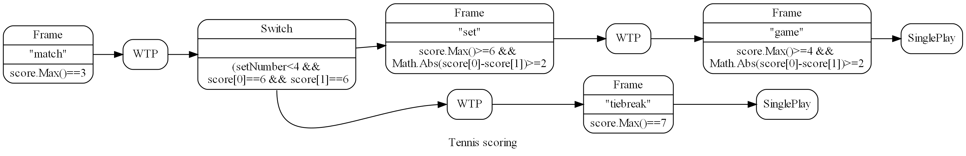
And here is the code version of that diagram. This application passes an exhaustive set of tests for the scoring of tennis.
private IConsistsOf match = new Frame("match")
    .setIsFrameCompleteLambda((matchNumber, nSets, score) => score.Max()==3)
    .WireTo(new WinnerTakesPoint("winnerOfSet")
        .WireTo(new Switch("switch")
            .setSwitchLambda((setNumber, nGames, score) => (setNumber<4 && score[0]==6 && score[1]==6))
            .WireTo(new Frame("set")
                .setIsFrameCompleteLambda((setNumber, nGames, score) => score.Max()>=6 && Math.Abs(score[0]-score[1])>=2)
                .WireTo(new WinnerTakesPoint("winnerOfGame")
                    .WireTo(new Frame("game")
                        .setIsFrameCompleteLambda((gameNumber, nBalls, score) => score.Max()>=4 && Math.Abs(score[0]-score[1])>=2)
                        .WireTo(new SinglePlay("singlePlayGame"))
                    )
                )
            )
            .WireTo(new WinnerTakesPoint("winnerOfTieBreak")
                .WireTo(new Frame("tiebreak")
                    .setIsFrameCompleteLambda((setNumber, nBalls, score) => score.Max()==7)
                    .WireTo(new SinglePlay("singlePlayTiebreak"))
            )
        )
    )
);
And just like that we have a full featured executable tennis scoring engine.
4.21.2. Final notes
Notice that I have added string names to the instances of Frame and other objects. This is not required to make the program function, but generally is a good habit to get into in ALA. It is because in ALA we typically use multiple instances of abstractions in different parts of the program. The names give us a way of identifying the different instances during any debugging. Using them I can Console.Writeline debugging information along with the object’s name.
Around 8 lines of code express the rules of ten-pin bowling and around 15 lines of code express the rules of tennis. That sounds about right for the inherent complexity of the two games. The two rule descriptions actually execute and pass a large battery of tests.
The domain abstractions are zero-coupled with one another, and are each straightforward to write by just implementing the methods of the IConsistOf interface according to what the abstraction does. The abstractions are simple and stable. So no part of the program is more complex than its own local part.
The domain abstractions are reusable in the domain of game scoring. And, my experience was that as the details inside the abstractions were implemented, the application design didn’t have to change.
Why two example applications? The reason for doing two applications in this example is two-fold.
-
To show the decreasing maintenance effort. The Tennis game was done easily because it reused domain building blocks we had already created for bowling.
-
To emphasis where all the details of the requirements end up. The only difference between the bowling and tennis applications is the two diagrams, which are translated into two code files: bowling.cs and tennis.cs of 8 lines and 15 lines respectively. These two files completely express the detailed requirements of their respective games. No other source files have any knowledge of these specific games. Furthermore, Bowling.cs and Tennis.cs do not do anything other than express requirements. All implementation to actually make it execute is hidden in domain abstractions and programming paradigm abstractions.
Here is a link to the code on Github: GameScoring code
5. Chapter five - Methodology
5.1. The first few strokes
As a software engineer contemplating a new project, I have often asked myself "Where do I start?" This also happens with legacy code, when contemplating the direction that refactorings should take. "If this software were structured optimally well, what would it look like?"
Christopher Alexander, the creator of the idea of design patterns in building architecture, said, "As any designer will tell you, it is the first steps in a design process which count for the most. The first few strokes which create the form, carry within them the destiny of the rest". This has been my experience too.
In Agile, where architecture is meant to emerge, this wisdom has been lost. ALA restores that wisdom to software development, and gives the software architect the exact process to follow for that little piece of up-front design. No more than one sprint is required to do this architectural work, regardless of the size of the project.
Furthermore, once this architectural work is done, the Agile process works significantly better thereafter.
My experience over several projects so far is that the initial architecture does not need to change as the development proceeds if good quality abstraction are invented.
There is one aspect of ALA that is hard to master - the invention of appropriate abstractions in a new domain. The reason why the "standard deviation uses squareroot" example seems easy is that the squareroot abstraction was already invented, and we already know it. In ALA you will need to invent your own domain level abstractions. In other engineering disciplines, new abstractions come along only every few years, or hundreds of years sometimes. In software engineering, we have to do it every day in the first two weeks of a project in a new domain, and probably every iteration after that for a few iterations. But all whom I have taught how to do this have found it worth the effort, and all get much better at doing it. Working in the resulting zero-coupled code becomes a joy.
5.2. Agility
ALA is inherently optimally agile (except for an Iteration zero which we will discuss next). By optimally agile, we mean that the amount of code that changes to change functional requirements is the minimum it can be. The amount of code that actuall depends on requirements is a small percentage of the total. This differs from the average application where most code depends on the requirements.
ALA achieves this at its first level of separation of concerns. This first separation is to separate code that will just describe requirements from code that will implementation the abstractions needed to describe the requirements. This implementation code never has knowledge of any requirements, so it generally doesn’t change when requirements change. Only the code that describes requirements needs to change, and that code is optimally minimal.
5.2.1. Iteration zero
When a new project begins, the only new information we have is the requirements. Any design decisions that don’t depend on the specific requirements could already have been made beforehand. It is those decisions that form the ALA reference architecture. Therefore, when we get the requirements, that is our immediate and total focus. We may not know all of them, but we will only need a sample to build start inventing our domain abstractions.
Looking at the available new information as a whole first instead of taking it a bit at a time during the project’s sprints will make a huge difference to the quality of the abstractions we invent, and eventually the quality of the application’s architecture.
The process in the first iteration takes requirements one by one, and represents them, in all their detail. Domain abstractions will be invented as you go, and they will have parameters or properties that will handle those details from requirements.
For the first green field application, you spend a maximum of one sprint. After that you do need to find out if your design works. So you may not get through all the known requirements. That does not matter.
To know whether knowledge from your design goes in the application layer or the domain abstractions layers, you consider what the scope of that knowledge is. Is the knowledge specific to this one requirement in the one application, or is it potentially reusable in the same or other applications? A softkey label is clearly specific and goes in the application. The concept of softkeys is clearly a domain abstraction.
The output of the first sprint does not implement any of the invented abstractions, but it does include all details of the requirements that are looked at. In so doing, you design the first approximation of a DSL. The DSL may be refined later as more requirements are looked at.
Each abstraction will eventually be implemented as a class, but initially we just record the names of the abstractions, and a short explanation that provides the insight into what the abstraction does.
By the end of the first sprint the requirements will have become easier and easier to represent, as the set of abstractions will have taken shape. Sometimes you will generalise an abstraction further to enable it to be useful in more parts of the application.
By keeping moving through the requirements at a much faster pace than in normal development (say one feature per hour instead of one per week), we can keep representing them in a coherent way, revising abstraction ideas we have already invented. Ideally, we will end up with a set of domain abstractions that can be wired together in different ways to represent the requirement space - the space of all possible requirements. That space, which we call the domain, will grow slightly as time goes on and it accommodates a growing family of products, but we don’t want it to grow beyond that. We don’t want to invent ways of implementing things we will never do.
On the other hand, we do want to invent quite a few abstractions during this first iterations so that we end up with a coherent set of them that will compose together in an infinite variety of ways.
The output of sprint zero is usually a diagram showing the wiring of instances of abstractions, together with configuration information for those instances.
It doesn’t matter if some of the requirements are wrong. Chances are they are still useful for scoping out the domain space. What we are actually producing in this phase are the necessary abstractions for the Domain Abstractions layer. If the requirements change later, it will be trivially simple to change them as only the Application layer wiring should change.
Once this process has started to become easy, which should happen within the first sprint, the burning question in our minds will become “Will all this actually work?” We have to trust that there will be a way to write those abstractions to make the whole system execute.
5.2.2. How to invent Domain Abstractions
The most difficult part for people new to ALA is the skill of inventing the domain abstractions. You can fully understand the theory of ALA and why we need to invent abstractions, and still find it tricky to actually invent them. That’s because in this step in the process, we have to literally become inventors who are adding to the state of the art within your domain.
So the biggest insight I can offer here is don’t expect it to come without effort. Put your inventors hat on. Deliberate about the problem over a long period of time. Leave it overnight. Come back to it afresh in a week. Be patient.
I sometimes find that a solution will pop out of nowhere while reading about something completely unrelated. Once the human mind has been deliberating for some time, it remembers the whole context of the problem, and seems to carry on pattern matching for potential solutions in the background. I am reminded of the story of the Dam Busters. The British wanted to bomb the German dams to flood the industrial valleys below them. They worked out that they could deliver the bombs to the face of dam by skipping them across the surface of the lake. But they couldn’t get their bomber low enough to the water at night to get them to skip, because they had no way of knowing their height above the water.
Then one of the pilots was attending a play. He saw the spotlights pointing at the actor from different angles. And suddenly he had the solution. By mounting spotlights at the nose and the tail of the aircraft at a certain angle, they would know when they were at the correct height when the two spots came together at the surface of the water.
In my experience, there is always a solution, and it is always worth the effort. Just as good inventions are like gold, good abstractions are like gold in your application.
This section offers some practical tips on where to start.
-
You start by simply expressing requirements. You are inventing domain abstractions to allow you to express the requirements succinctly, but including all their details.
-
Draw a diagram that describes the requirements. You will draw boxes with lines. The boxes are your invented domain abstractions. The lines are your invented programming paradigms.
-
Look at the English version of the requirements for words that recur. These are candidates for abstractions.
-
Your diagram should have about the same amount of information as the English requirements. It will be succinct, even though it will include lots of detail such as text strings that come from requirements. Anything else that even begins to look like implementation or how it will work or execute is the beginning of an idea for an abstraction. Don’t worry about them. Just concentrate on making a description of requirements.
-
Always keep in mind that reusability and abstraction are two sides of the same coin. Your invented abstractions are anything that is potentially reusable.
-
Start with the user interface. Sketch multiple parts of the UI to make it more concrete. Then it is relatively easy to invent abstractions for your UI. They are things that will recur in different parts of the UI that you will always want to be done the same way. We can draw inspiration from the many widgets we already find in UI frameworks. ALA will often have equivalent ones that are just a little more specialised to your domain. Buttons may have a consistent size and style in your domain. Or your domain may need Softkeys, which are not usually part of a UI framework.
ALA UI abstractions will usually be composed together in a tree structure representing the containment structure. This is similar to the tree structure of XAML, but in ALA we will usually do it as a diagram that is just one part of the entire application diagram.
-
Once you have designed some UI, you will then want to connect the UI elements that display data to some data sources. These data source are candidates for abstractions. For example, a data source that represents a disk file can be an abstraction that handles a disk file format. You will start to have dataflows between instances of data sources, be they UI elements or other source/destinations.
-
Between your data end points, data may need to be transformed, aggregated, filtered, sorted, validated or transacted (transacted means either all of it or none of it). All of these are great candidates for domain abstractions.
-
Sometimes a data source or destination will involve a protocol. A protocol is a domain abstraction. One abstraction should be invented to know about the protocol so that no other abstraction needs to know anything about the protocol. Sometimes there are protocols on top of protocols. For example, on top of a serial data stream protocol such as line terminated text, you may have another protocol that specifies the expected content of the first line.
This same idea applies to file formats. A file format, such as a CSV file becomes an abstraction. If there is further formatting expected on top of the basic CSV format, such as a header row, that becomes a second abstraction.
As with all abstractions, these abstractions know all about the details of something, e.g. a protocol or a format, and become the only thing in the entire application that does know about it.
As a result these types of abstractions will usually handle the data going in both directions - sending and receiving, reading and writing.
-
If you have hardware devices, each will become an abstraction. For example, an ADC device will become a domain abstraction. The abstraction will know all the detail about the device (everything that is in the datasheet for the device). No other part of the program will know these details.
If you have an ADC device that has an SPI interface, that will become two abstractions, one that knows all the details of the device, and one that knows all the details of the basic SPI interface.
-
Sometimes a section of requirements will seem like it should become a 'module' or 'function' - for example to parse a string. Try to turn the module or function into something more generally useful. Even if you still end up having only one instance of it for now, by separating that module or function into a general part and a configuration part (that has the information for it’s specific use in the one part of your application), you will make the general part easier to know what it does - simply because it is more abstract. In time you will often generalise it further and start to have instances of it elsewhere.
-
If all else fails, just start writing code that implements the requirements in the old fashioned way, not worrying about how messy it gets. When it is functioning as you want, then refactor it to ALA as follows. This is actually quite a straightforward process.
Any code that has details that come from requirements, move that to the application layer, leaving behind generalised functions or classes that have parameters or configuration properties that the application will pass in.
At first the generalised classes may have only one instance each. Look for ones that have similar functionality and combine them. The difference between them become further configuration properties, sometimes in the form of lambda expressions.
Now refactor the generalised classes or functions so that they do not call each other directly.
-
In the case of functions, this step will involve adding new 'wiring' parameters that themselves take functions. The application will pass in the function that it needs to be wired to. These wiring parameters will usually either be to pull the input or push the output. The wiring function signatures should be even more generalised to allow Lego-like composition of functions by the application. They become interfaces in the programming paradigms layer. Section 1.11 has a worked example of refactoring of functions to ALA.
-
In the case of classes, this step will involve adding dependency injection setters. These will be used by the application to specify what class and instance it will talk to. This step removes all uses of the "new" keyword from the class (except ones that are instantiating classes in a lower abstraction layer such as your framework).
If you have any uses of the observer pattern (publish/subscribe pattern), move the code that does the actual registering or subscribing up to the application. Provide a dependency injection setter for it to use.
The dependency injection setters should all take generalised interfaces as thier parameter to allow Lego-like composition of class instances by the application.
-
Your classes and functions are now proper abstractions because they don’t know anything about the outside world, including who they are wired to, making them reusable.
5.2.3. 2nd Sprint
In the second sprint we start converging on normal Agile. You pick one feature to implement first. Agile would say it should be the most essential feature to the MVP (minimum viable product), but this can be tempered by the need to choose one that requires a fewer number of abstractions to be implemented. Next, you design the interfaces that will allow those abstractions to plug together according to the wiring you already have from the first sprint. What messages will these paradigm interfaces need to pass at runtime between the unknown clients to make them work?
It may take several sprints to produce the first working feature, depending on the number of abstractions it uses.
At first this sounds as if it might be just the waterfall method reincarnated. Do an overall design, document it or model it, and then write lots of code before everything suddenly starts working. But the design we created in iteration zero is very different from what a normal waterfall would produce, and is resilient to the sorts of problems waterfall creates. Instead of a ‘high level’ design of how the implementation will work which is lacking in detail, the design is a representation of requirements, in full detail. The design is not a model. It is executable.
There is one more important thing that the design phase in Iteration Zero does. While it deliberately doesn’t address any implementation, it does turn the remainder of the implementation into abstractions, and those abstractions are zero coupled. To convert from executable to actually executing, it only remains to implement these now completely separate parts. You can give these abstractions to any developer to write. Together the developers will also easily be able to figure out the paradigm interface methods needed to make them work, and the execution models to take care of the execution flow through them with adequate performance.
Often when a project is split into two phases, the first phase turns out to be waste. The devil is in the details so to speak. This happens because the implementation details in phase two are coupled back to and affect the design in phase one. As learnings take place during implementation, the design must change. In ALA the output from phase one is primarily abstractions, which are inherently stable and therefore hide details that can’t affect the overall design. If the abstractions are good, phase two will typically have little effect on the work done in phase one.
Once the first feature is working, several abstractions will have been implemented. The second feature will take less time because some of the abstractions are already done. In ALA velocity increases as time goes on and keeps increasing until new features only involve instantiating, configuring and wiring domain abstractions in new ways. This velocity acceleration is the complete opposite of what happens in monolithic code.
5.2.4. Later sprints
Imagine going into a sprint planning meeting with a Product Owner, a small team of developers, and a mature ALA domain that already has all the common domain abstractions done. As the Product Owner explains the requirements, one of the team members writes them down directly as they would be represented in terms of the domain abstractions. Another team member watches and remembers any lost details without slowing the product owner down. A third member implements the acceptance tests in similar fashion, and a fourth provides him with test data. It would be nice to have a tool that compiles the diagram into the equivalent wiring code. With such a tool, the team could have it executing by the end of the meeting. At the end of the planning meeting the development team say to the product owner "Is this what you had in mind?". The team can get immediate feedback from the Product Owner that the requirements have been interpreted correctly.
Of course, the planning meeting itself would only produce 'normal' functionality. Usually it is up to the development team, not the Product Owner, to uncover all the abnormal scenarios that can happen, and that is usually where most of the work in a software system goes. Having said that, in a mature domain, the validation of data already has decorator abstractions ready to go.
The graph shows the effort per user story against months into a green-field project. The left axis is arbitrary - the shape of the curves is what is important. For a big ball of mud, experience tells us that the effort increases dramatically and can asymptote at around 2 years as our brains can no longer handle the complexity, and the project must be abandoned.
The COCOMO model, which is an average of industry experience, has a power relationship with program size, with an exponent of around 1.05 to 1.2. I have used the mid point, 1.1, for this graph. The model appears to imply that getting lower than 1.0 is a barrier, but there is no reason to believe this is the case. Reuse can make the power become less than 1. The range of 1.05 and 1.2 probably results from some reuse mitigating some ever increasing complexity.
ALA takes advantage of the fact that zero-coupled abstractions can keep complexity relatively constant and drastically increase reuse. A spectacular fall in effort per user story is thus possible.
5.3. Technical debt
Technical debt is real. Convincing your non-technical manager that it is real is not realistic, especially when you tell him that this is based on estimates. He already knows about your 'estimates'. Even if you could measure it, and offer your manager a payback period for a one-day investment in refactoring, there is a problem. He is measured on this sprints performance. Or he is measured on some other criteria such as this years budgeted sales. Technical debt is tomorrow’s problem, and that is not his problem, not ever.
A better answer would be to not generate technical debt in the first place. In Agile we are taught that the architecture depends on the what we learn as we write the code. The Definition of Done is supposed to tell us to clean it up as we learn. But it is also possible that we will learn something that requires previous sprint’s of work to be cleaned up. A refactoring could need changes to the structure at the largest granularity level.
So here is a better solution. What if, as far as possible, we know a meta architecture that all software programs should follow. It is a big scale meta-architecture, so it gets things into the right places in the big scale.
So now you just get it right in the first place. Isn’t that better?
Now some will argue that they do that already. Their large scale structure is layering, or it is MVC or it something else. I have been told that this doesn’t work because we fail to actually keep to the prescribed architecture. But think it is because up till now, these architectural patterns have not worked very well.
5.4. Folder structure
[tree,file="folderstructure.png"]
root
|--Application1
|  `--application.cpp
|--Application2
|  `--application.cpp
|--DomainAbstractions
|  |--abstraction1.cpp
|  |--abstraction1.h
|  |--abstraction2.cpp
|  `--abstraction2.h
`--ProgrammingParadigms
   |--Paradigm1.h
   `--Paradigm2.h
This is a suggested folder structure for ALA. Because ALA does not use decomposition, you don’t end up with components that are contained by the applications, so there are no subfolders under the application. Instead, you end up with Domain Abstractions outside the application, so they go in their own folder in a flat structure.
Similarly, the Programming Paradigms code is not contained by an application, or even by the domain, so would not be contained by the domain’s projects folder.
5.5. Convention over configuration
When the application create an instance of an abstraction, most of the configuration of that abstraction should have defaults. In ALA, setters allow optional configuration, reducing the amount of information that would otherwise be required in the application to fully configure each abstraction. Any configuration that we wish to enforce goes into the constructor.
There is a counter argument that says that all configuration should be explicit so that nothing can be forgotten. ALA prefers optional configuration because we want the application to just express the requirements. Also optional configuration allows abstractions to default to their simplest form, making them easier to learn.
5.6. Knowledge prerequisites.
When other programmer are doing maintenance on your code, you should make sure they have the knowledge they need. They will need knowledge of ALA. They will need to know about the programming paradigms used. They will need to know about the domain abstractions, and the insight of what each one does. And then they should know that the application diagram is the source code. It is up to you that every develop that follows will know all this.
5.6.1. Intellisence
After they have modified the diagram, the maintaining developers will need to manually modify the corresponding code. Here they will see instances of abstractions being used all over the place, either 'new' keywords or function calls. If we have done our job with knowledge prerequisites, they will have been introduced to these abstractions. However, it doesn’t hurt to have brief reminders of what they are pop up when the mouse is hovered over them. So put in triple slash comments (or equivalent) describe the abstraction succinctly, with the intention of it being a reminder to someone who has already met the abstraction. Put a full explanation in the remarks and examples sections.
The class name after a new keyword is actually the constructor name, so you must duplicate the summary section there. Often in ALA, the class name is not referred to at all in the application.
5.7. Two roles
ALA requires two roles. Both can be done by the same person, but always he should be wearing only one hat at a time. There is the role of the architect, and the role of the developer.
The role of the architect is harder than that of the developer, that’s why we have the role. Expect it to be hard. Perhaps, surprisingly, the architect’s main job is to focus on the requirements, and the developers main job is to implement the abstractions (which know nothing of the requirements). In describing the requirements, the architect invents domain abstractions.
The architect also has a role in helping the developer to design the interface’s methods. In other words, how at runtime the system will be made to work.
This aspect of ALA can also be difficult at times. I have sometimes got stuck for a day or so trying to figure out how the interfaces should work, while still keeping them more abstract than the domain abstractions. The ALA constraints are that these interfaces should work between any two domain abstractions for which it may be meaningful if they are composed together in an application. However, the problem has always been solvable, and once solved, it always seems to have a certain elegance, as if you have created a myriad of possibilities at once. Implementation of the interfaces by the relevant domain abstractions becomes easy. Development then proceeds surprisingly quickly.
5.8. Example project - Calculator
This project was originally done in a hurry for an ALA workshop. Apart from being a cool example of the use of ALA, the calculator itself is cool. This calculator is in Github, as a work in progress here: https://github.com/johnspray74/ReactiveCalculator
The original development for the workshop was done in about a day, so here we tell the story of that development.
When I was first asked to do the workshop, I needed to think of a suitable pedagogical sized project. It was suggested to do a calculator. Ok, I thought, if we have the domain abstractions already in place before the workshop, we should be able to write a calculator application (top layer) during the workshop.
When we think of a calculator application, we usually imagine a user interface that mimics a handheld calculator. It has a one line display and a keypad on the screen. We certainly could have built that calculator (primarily using a state machine programming paradigm). But that problem has already been solved by Miro Samek. Besides, I hate those simulated handheld calculators. I think they are a stupid way to do calculations on a computer. Such a calculator would be cumbersome.
As an aside, I once loved HP calculators. The first programmable anything I ever owned was an HP65 calculator. I have owned many top end models at one time or another. But as their displays got larger, I became more and more disappointed with how they used that display real-estate. They just used it as a stack.
The calculator I wanted would show the expression you had entered so you can check it. It could show it in algebraic or even textbook form, even though you had entered it as RPN. You could re-edit the expression. You could label your expression result and then you could use the result in another expression. When you changed something, all results would be updated like in Excel. This is what the HP prime should have been.
So I drew this sketch of what I wanted a calculator to be:
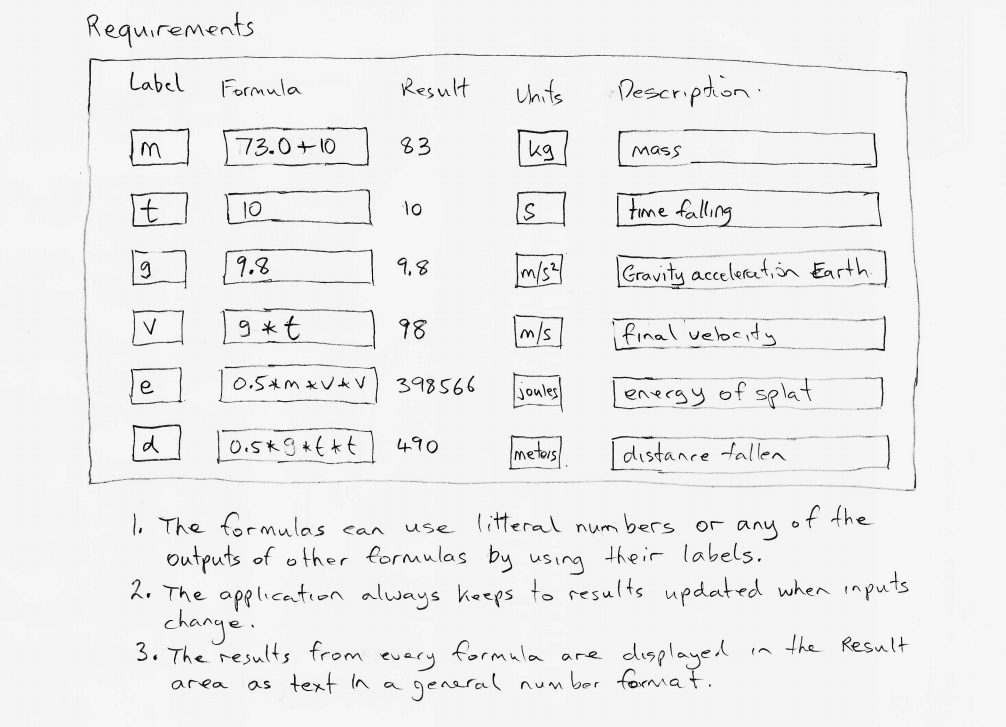
Here is a screenshot of the working calculator as it was two half-days later:
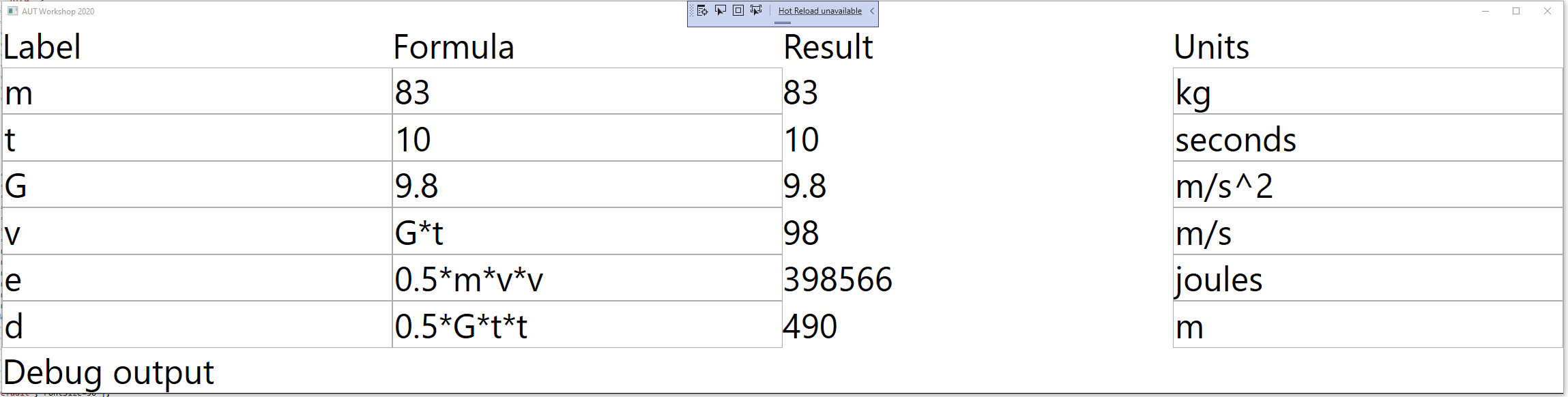
The first step in the design of the calculator was to express the requirements (UI plus behaviours), inventing any needed abstractions to do so. Here is the actual first sketch I drew:
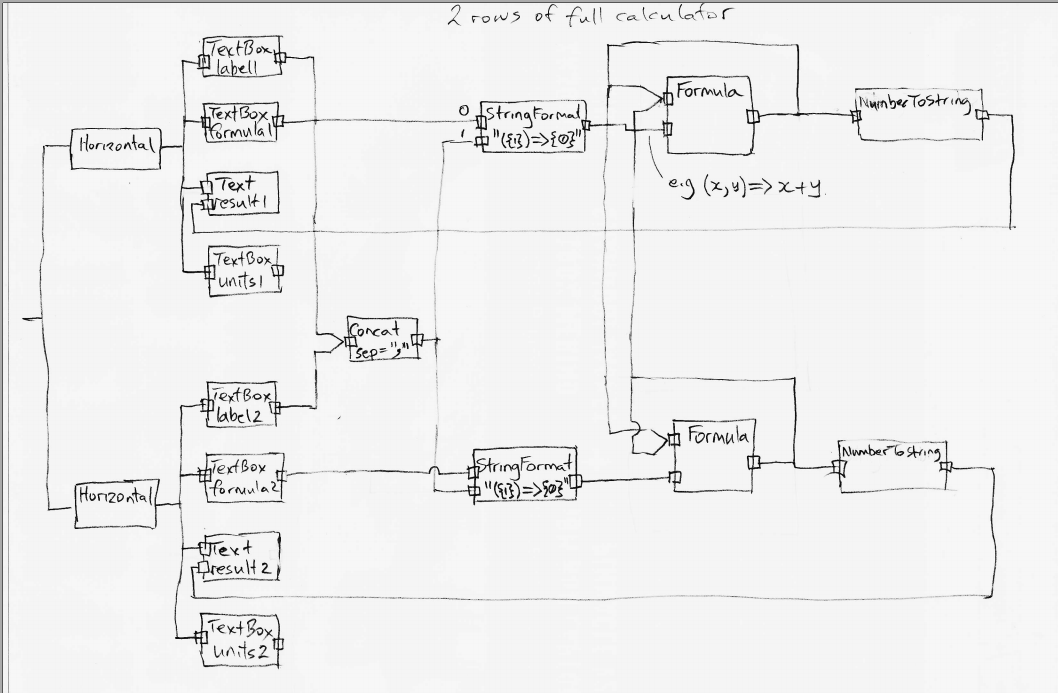
As we shall see, this diagram is practically executable code. The calculator is practically done. We don’t know if the invented domain abstractions will work yet, but let’s go through how this calculator works anyway.
5.8.1. How the calculator works
First notice how the entire calculator is there. Every detail for this particular calculator is represented in the diagram. All those details cohesively describe the calculator. This is an important aspect of ALA designs. All the UI and all the dataflows to make a working calculator are in this one diagram. What is not here is the details we left to the domain abstractions. None of these abstractions is specific to a calculator. They can be used for all sorts of things. Even the Formula abstraction would be useful in any application where a calculation needs to be changed at run-time. For example an insurance application may need configurable calculations.
The left side shows two instances of the abstraction, Horizontal. These arrange their children horizontally in the UI. To the left of those (not shown) is an instance of Vertical, which arranges the two Horizontals vertically. And to the left of that, also not shown, is an instance of MainWindow.
Each Horizontal has 3 instances of TextBox and one Text. The TextBoxs allow you to enter a string. The abstraction, Text, can only display a string. I see at this point, I hadn’t put in the TextBox for the description.
We can ignore the use of labels for a moment and just enter a formula containing constants into the first row TextBox. Let’s say we type in "2+1". The string "2+1" goes along the dataflow wire to the StringFormat instance on its port 0. The StringFormat is configured with the format string "({1}⇒{0})". StringFormat uses this format string in the same way as an interpolated string in C#. The {0} is substituted with the string coming in on port 0. The {1} is substituted with the string coming in on port 1. Since we have no string on port 1, the output from the StringFormat will be "()⇒2+1". This is simply a lambda expression with no parameters. This string is fed into the instance of Formula. Formula is an abstraction that knows how to evaluate a lambda expression. Actually it will accept just a formula string (such as "2+1") as well. We can ignore the other input of Formula for the moment. Formula will evaluate "()⇒2+1" and produce the number 3 on its output. This output is a dataflow of type double. This number is fed to an instance of NumberToString, and from there it goes to the instance of Text that knows how to display a string.
Now let’s follow the use of labels in the calculator. Let’s put the labels "a" and "b" into the TextBoxs for labels on the two rows. "a" and "b" are fed to the Concat instance. Concat’s input port can have any number of string dataflows wired into it. In this diagram it has only two. What Concat does is concatenate all its inputs adding a separator. In this case the separator is configured to be a comma. The output of the Concat is "a,b". The concatenated list of labels is fed into port 1 of both StringFormat instances.
Now let’s put the formula "a*3" into the 2nd row of the calculator. The output of the StringFormat for that row will be "(a,b)⇒a*3". That lambda expression will be fed to the Formula instance, which will evaluate it, using the value on its first input port for the value of 'a'. The output will appear on the corresponding Text in the 2nd row.
So that’s all there is to understanding how the calculator works. At this point it takes a leap of faith that the abstractions can all be made to work, and that the two programming paradigms used, the UI layout and the dataflow, can be made to work. Not withstanding that, all the information required in the design of the calculator is captured.
At this point I drew little drawings of all the invented abstractions. Actually I reused TextBox, Text, Vertical, Horizontal and FormatString from a previous project. And I had already made the UI and dataflow programming paradigm interfaces in previous projects, so I reused them as well.
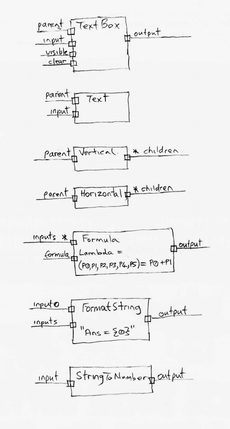
I see I forgot to draw Concat. I had to write that one. Here is its template as it was in my Xmind templates diagram.
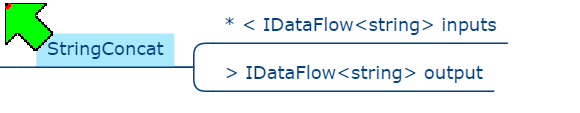
The two ports are both drawn on the right hand side unfortunately - a limitation of using Xmind as the drawing tool. Drawing the templates makes the abstractions clearer for their implementation.
5.8.2. Implementing the domain abstractions
Abstractions are generally trivial to implement because they are zero coupled with anything. They are like tiny stand-alone programs. Here is the full code for StringConcat.
using ProgrammingParadigms;
using System;
using System.Collections.Generic;
using System.Linq;

namespace DomainAbstractions
{
    /// <summary>
    /// Outputs the input strings concatenated together
    /// Whenever an input strings changes, a new output is pushed.
    /// ---------------------------------------------------------------------------------------------------------
    /// Ports:
    /// 1. List<IDataFlowB<string>> inputs: inputs (indefinite number of string inputs)
    /// 2. IDataFlow<string> output: output
    /// </summary>


    public class StringConcat
    {
        // Properties ---------------------------------------------------------------
        public string InstanceName { get; set; } = "Default";
        public string Separator { private get; set; } = "";

        // Ports ---------------------------------------------------------------
        private List<IDataFlowB<string>> inputs;
        private IDataFlow<string> output;


        /// <summary>
        /// Outputs a boolean value of true when all of its inputs are true. Null inputs are treated as false.
        /// </summary>
        public StringConcat() { }

        // This function is called immediately after each time the inputs port is wired to something
        private void inputsPostWiringInitialize()
        {
            inputs.Last().DataChanged += () =>
            {
                var result = "";
                bool first = true;
                foreach (IDataFlowB<string> input in inputs)
                {
                    if (!first) result += Separator;
                    first = false;
                    result += input.Data;
                }
                output.Data = result;
            };
        }

    }
}
The code in Concat is straightforward if you know C#, except for a few conventions which are to do with the use of ALA (which I was already proficient with):
-
We put a property "InstanceName" in every domain abstraction. It’s not required, but the reason is because abstractions get reused. So you are likely to end up with multiple instances of an abstraction all over your application. If you name the instances, it makes debugging a lot easier because you can see it in the debugger and know which instance you are in.
-
All the IO for the abstraction is in a section called "Ports". Usually an abstraction would have some ports that are private fields of the type of an interface, and some that are an implemented interface. It just so happens that StringConcat has no implemented interface ports.
-
The two ports are private, and yet they get wired by the application code to other objects. This may seem a little bit magic. The reason they are private is to indicate they are not for use by anything else. The application will use a method called WireTo() to achieve the wiring. WireTo is an extension method on all objects. It uses reflection to find and assign to these "port" fields.
-
Notice that the "inputs" port uses IDataFlowB (not IDataflow). The B on IDataflowB indicates a tricky workaround for a limitation in the C# language. What we would have liked to do is implement IDatFlow. But we would have needed to implement IDataFlow multiple times. You can’t do that in C# (although there is no reason why not in theory, and hopefully all languages will have this feature to support the concept of ports one day).
-
Notice that the method, inputsPostWiringInitialize, is private and apparently unused. When the WireTo operation wires a port "xyz" it looks for a private method called xyzPostWiringInitialze and invokes it immediately. This gives us the opportunity to set up handlers on any events that may be in the interface. In this case, the IDataFlowB interface has a DataChanged event (that tells us when there is new data on the inputs).
-
It doesn’t make sense to use a StringConcat without wiring its output to something. So the line "output.Data = result" will throw an exception if the application has not wired it. Often times, abstractions have ports that are optional to wire, in which case we would use "outputs?.Data = result"
For reference, here is the IDataFlow interface, which lives in the ProgrammingParadigms folder, and is used by most of the domain abstractions including the StringConcat abstraction:
namespace ProgrammingParadigms
{
    public interface IDataFlow<T>
    {
        T Data { get; set; }
    }
}
As you can see, this interface is simple, but its importance in giving us a dataflow programming paradigm is huge. It allows objects to be wired together so that data can flow from object to object without the abstractions knowing anything about each other. Note that IDataflow uses a 'push' execution model. This means that the source always initiates the transfer of data on its output (by using 'set'). The IDataFlowB interface is a little more complicated, so we wont go into how it works just now. But it achieves exactly the same purpose of the dataflow programming paradigm, just in a different way that allows more than one input port of the same type. .
The other domain abstraction I needed to write for the first time was Formula. Here is the template as used in Xmind:
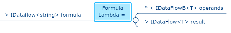
Once again, one of the input ports is shown on the right when we would prefer it to be on left.
Formula can be configured with an optional C# lambda expression when it is instantiated by the application, for example:
new Formula() {Lambda = (x,y) => x+y; }If used in this way, the formula is fixed at design-time. But its real power comes from the fact that it can take a formula as a string at run-time. Formula has an input dataflow port called "formula".
The Formula abstraction has to parse the formula string and then evaluate it. I used Roslyn to do this in a few lines of code. These lines of code took me a few hours to figure out however:
using Microsoft.CodeAnalysis.CSharp.Scripting;
using Microsoft.CodeAnalysis.Scripting;
using static System.Math;

namespace DomainAbstractions
{
    using LambdaType = Func<double, double, double, double, double, double, double>;

    public class Formula
    {
        public LambdaType Lambda { private get; set; }


        // Other code omitted from here


        private async void Compile(string formula)
        {
            var options = ScriptOptions.Default;
            options = options.AddImports("System.Math");
            try
            {
                Lambda = await CSharpScript.EvaluateAsync<LambdaType>(formula, options);
            }
            catch (CompilationErrorException e)
            {
                Lambda = null;
            }
        }
    }
}
As you can see, currently the Formula abstraction can only handle formulas that use a maximum of six parameters. The calculator application can use any number - it’s just that any one formula is limited to using only six.
The rest of the code in the Formula abstraction is mostly dealing with this requirement of exactly six parameters used by LambdaType. But that’s all internal to the abstraction. An instance of the Formula abstraction can handle any number of operands from zero to many. The Formula abstraction is also tolerant of the string on the formula input port being either just a formula such as "2*(3+1)" (implying it’s not using any operand inputs), or a proper lambda expression such as "(x,y,z)⇒x*(y+z).
Now that we have our needed domain abstractions, let’s return to the application layer, and see if we can get this calculator running.
5.8.3. Hand wiring the application code from the diagram
First here is the startup code for a wired ALA application. It is very simple:
namespace Application
{
    public class Application
    {
        private MainWindow mainWindow;

        [STAThread]
        public static void Main()
        {
            Application app = new Application();
            app.mainWindow.Run();
        }

        private Application()
        {
            // mainWindow = WireHelloWorld();
            mainWindow = Calculator2RowHandWired();
        }
    }
}
Here is an ALA Hello World application
private MainWindow WireHelloWorld()
{
    return new MainWindow().WireTo(new Text("Hello World"));
}
Ok, now we are ready to hand wire the hand drawn calculator diagram shown above:
private MainWindow Calculator2RowHandWired()
{
    // To understand this code, you need the wiring diagram of the two row calculator

    // First instantiate instances of abstractions we need to give names to. The rest can be anonymous.
    StringConcat stringConcat = new StringConcat() { Separator = "," };
    DataFlowConnector<string> stringConcatConnector = new DataFlowConnector<string>(); // Connectors are needed when there is fan-out or fan-in in the diagram
    stringConcat.WireTo(stringConcatConnector, "output");
    Formula[] formulas = { new Formula(), new Formula() }; // instantiate both the formulas up-front because we need to cross wire them


    MainWindow mainWindow = new MainWindow("Calculator")
        .WireTo(new Vertical()
            .WireTo(WireRow(stringConcat, stringConcatConnector, formulas[0], formulas))
            .WireTo(WireRow(stringConcat, stringConcatConnector, formulas[1], formulas))
            );
    return mainWindow;
}


private Horizontal WireRow(StringConcat stringConcat, DataFlowConnector<string> stringConcatConnector, Formula formula, Formula[] formulas)
{
    // To understand this code, you need the wiring diagram of the two row calculator

    // first instantiate objects we need to give names to.  The rest can be anonymous.
    Text result = new Text();

    // Wire up a calculator row
    Horizontal row = new Horizontal()
        .WireTo(new TextBox()
            .WireTo(new DataFlowConnector<string>()
                .WireFrom(stringConcat, "inputs")
            )
        )
        .WireTo(new TextBox()
            .WireTo(new StringFormat<string>("({1})=>{0}")
                .WireTo(stringConcatConnector, "inputs")
                .WireTo(formula
                    .WireTo(new DataFlowConnector<double>()
                        .WireFrom(formulas[0], "operands")
                        .WireFrom(formulas[1], "operands")
                        .WireTo(new NumberToString()
                            .WireTo(result)
                        )
                    )
                )
            )
        )
        .WireTo(result)
        .WireTo(new TextBox());
    return row;
}
Commentary on this wiring code
-
The code is written in "fluent style". This is possible because the WireTo extension method returns its 'this' parameter, allowing you to use .WireTo() multiple times on an instance.
-
The parts of the diagram that have a tree structure can be wired by using more .WireTos immediately inside the brackets of another WireTo. This is what causes the indented code.
-
The previous two points allow much of the wiring to be done without having to think up names for the instances. The instances are anonymous just as they were on the diagram.
-
Where the diagram has cross wires that formed a cycle, we need to give instances names so that we can complete all the wiring to them.
-
Sometimes the WireTo method is given the port name of the first object. These are used when WireTo may get the wrong port if it were left to use the port types alone. (If an abstraction has multiple ports of the same type, WireTo doesn’t know which port to use.)
-
Most abstractions have ports that can only be wired to one place, and ports that can only be wired from one place. (The UI abstractions are exceptions, for example, Horizontal can be wired to multiple children.) The hand drawn wiring diagram has several places where the wiring either 'fans out' from a port or 'fans in' to a port. Unfortunately C# does not support the concept of ports, so we improvise to make them work in normal C# code. The way this improvisation works for fan-in and fan-out is to use a connector.
-
For fan-out you wire the output port to a new Connector. Then you can wire the connector to multiple places.
-
For fan-in, the abstraction, instead of implementing the port, uses a list field of a type like IDataFlowB. The 'B" on the end means the flow of data is reversed from IDataFlow. Now to wire such an inputs port to an output port also requires a connector (a second use for connectors). When wiring an IDataFlowB, you wire from the input to the connector (the opposite way to the direction of dataflow unfortunately).
-
-
As a convenience, you can use WireFrom. It reverses the two operands being wired compared to WireTo.
Handwritten wiring code like the above can be managed for small applications. It is easy to get it wrong though. The code is not readable from the point of view of understanding the application. That’s what the diagram is for. So every time you make a change to the requirements, you need to do it on the diagram first, then update the hand-generated code. You are still better off doing this than not using ALA. If not using ALA, the relationships of the cohesive, explicit ALA diagram still exist, but they become obscurred and distributed inside your modules.
But we don’t have to hand generate code. At the time of writing a hand written graphical IDE is under development.
Here is the calculator row part of the diagram, which was successfully used to auto-generate code:
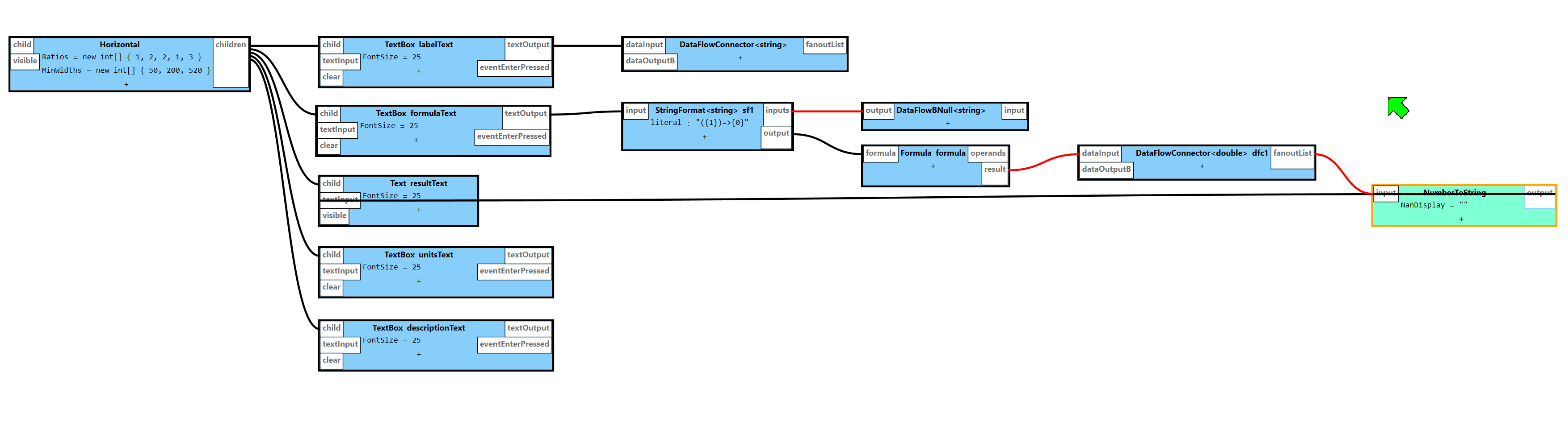
Before we had that tool, we used Xmind to do diagrams from which we could generated code. This is the approach described in the next section.
5.8.4. Automatic code generation from the diagram
Here is the diagram of the 2-row calculator as it was originally entered into Xmind. You can click on the image to get a bigger version.
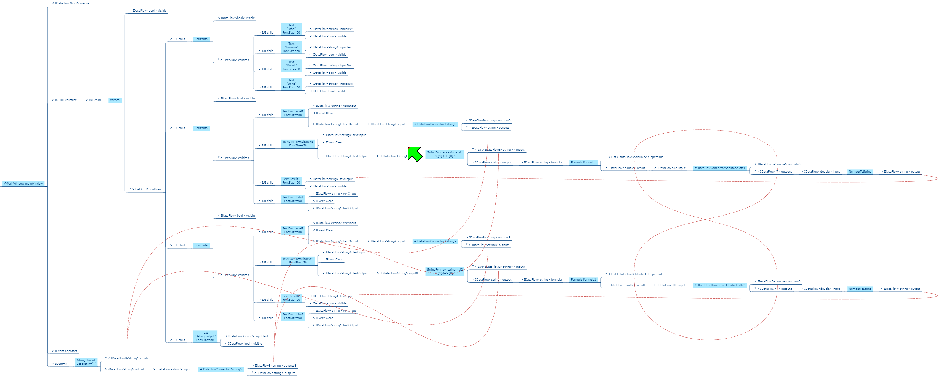
Xmind is not the perfect tool to do this, but it has one huge advantage - it lays itself out. This is so important that it’s why we use it (until our new tool is ready). We will put up with the disadvantages, and the necessary conventions until then. Those conventions are documented in the wiki section of the project in Github here: https://github.com/johnspray74/ReactiveCalculator/wiki
Entering the hand-drawn version of the diagram is a simple matter of copying and pasting the Xmind templates for the abstractions to the right place in the diagram. This connects most of the needed wiring from port to port. Xmind supports tree structured diagrams, so any cross tree wiring was done by using the red lines, which are quick to put in with a shortcut key.
The Xmind version of the diagram is pretty much identical to the hand drawn version. The colored boxes are instances of abstractions. All the other nodes attached around those colored boxes are the ports. The < and > signs in the ports are significant, and tell the automatic code generator which way to wire the instances. The asterisks are also significant, and tell the code generator that many wires can be wired to the one port.
The diagram done, it’s time to generate the code. A tool called XmindParser does this. It can be downloaded from the Github project main page. Here is the tool in use to generate a calculator from the diagram.
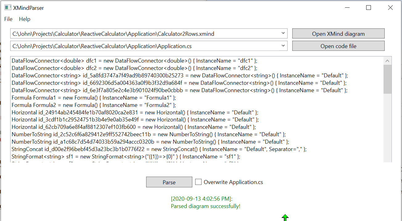
The tool can put the generated code into your Application.cs file if you give it special markers like the one below.
private void Calculator2Rows()
{
    // BEGIN AUTO-GENERATED INSTANTIATIONS FOR Calculator2Rows.xmind
    // END AUTO-GENERATED INSTANTIATIONS FOR Calculator2Rows.xmind

    // BEGIN AUTO-GENERATED WIRING FOR Calculator2Rows.xmind
    // END AUTO-GENERATED WIRING FOR Calculator2Rows.xmind
}
The markers contain the name of the Xmind diagram they get code from. This allows several diagrams to be used for one application.
I usually put the markers inside a function so that all the instantiated objects are private to the function.
Here is the code again with three lines of generated code shown in each section.
private void Calculator2Rows()
{
    // BEGIN AUTO-GENERATED INSTANTIATIONS FOR Calculator2Rows.xmind
    Formula Formula1 = new Formula() { InstanceName = "Formula1" };
    Formula Formula2 = new Formula() { InstanceName = "Formula2" };
    Horizontal id_24914ab245484fe1b70af8020ca2e831 = new Horizontal() { InstanceName = "Default" };
    // END AUTO-GENERATED INSTANTIATIONS FOR Calculator2Rows.xmind

    // BEGIN AUTO-GENERATED WIRING FOR Calculator2Rows.xmind
    mainWindow.WireTo(id_b02d2caea938499b997b9bfcb80fb0e9, "iuiStructure");
    id_b02d2caea938499b997b9bfcb80fb0e9.WireTo(id_24914ab245484fe1b70af8020ca2e831, "children");
    Formula1.WireTo(dfc1, "result");
    // END AUTO-GENERATED WIRING FOR Calculator2Rows.xmind

}
Completing the diagram had taken another morning of work. But the calculator was now working and I was ready for the workshop.
I made a diagram with six rows, but it was getting pretty large, and the duplication was pretty clumsy.
5.8.5. Calculator with 10 rows
The 6-row calculator is powerful compared to any normal calculator, but still wouldn’t do jobs like the one shown here which has 11 rows:
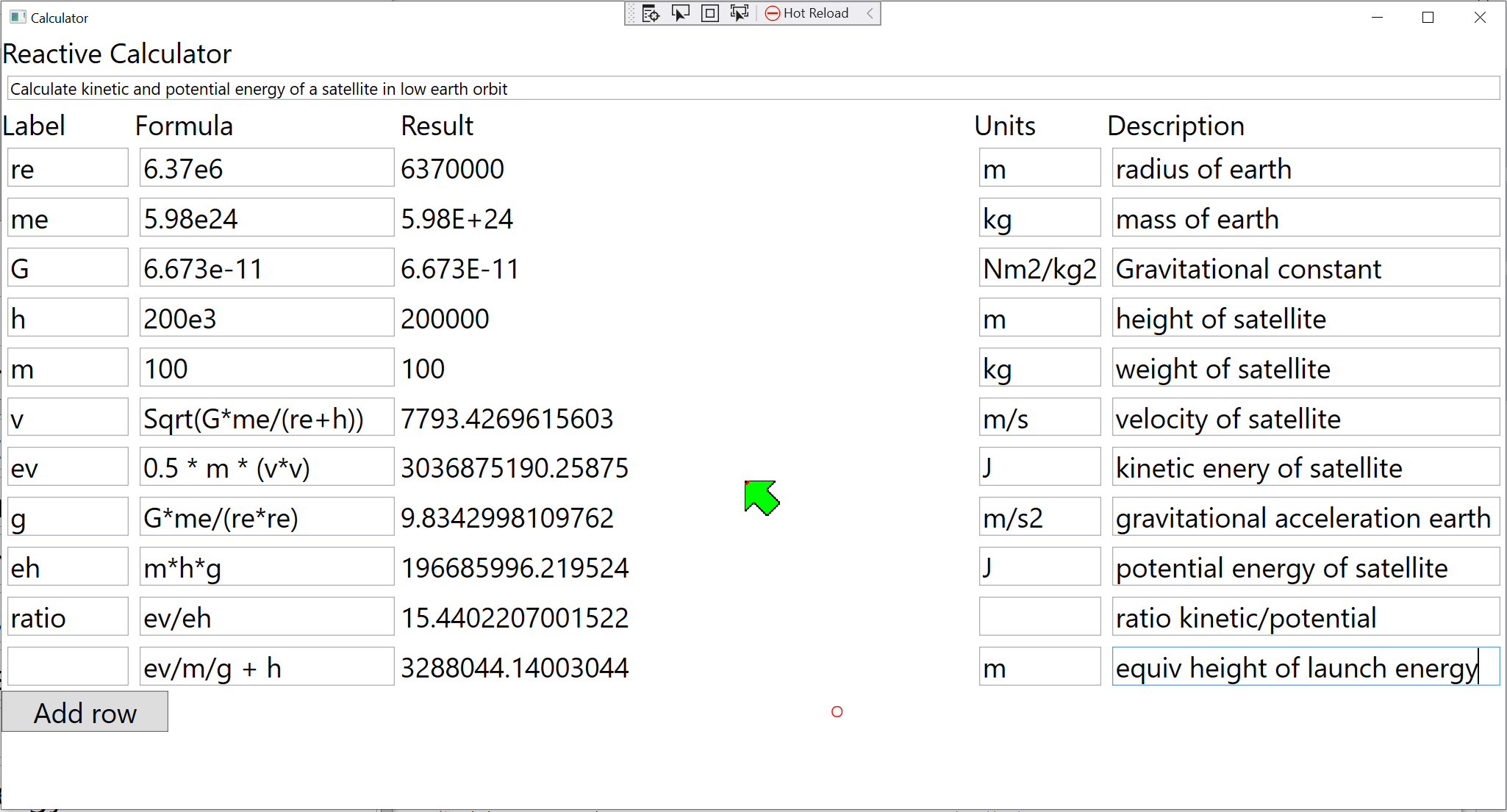
So it was time to do some maintenance, and solve that problem of the repetition in the diagram at the same time. During this maintenance, none of the existing abstractions changed. Their ports stayed the same. Their internals were improved a little in some cases but nothing significant. Formula was modified internally so that it could handle more than six operand inputs, although any one formula can still only use six of them.
There were two major changes though. One was to put the repeated wiring for a calculator row inside its own abstraction. This abstraction is called "CalculatorRow". This abstraction is less abstract than the Domain abstractions it uses, but more abstract than the application, which will use it multiple times. Other version of the calculator alos reused it. So it goes into its own layer between the two. This new layer is called "Requirements Abstractions". We don’t make new layers lightly, but we had had the experience in a larger project that the diagram got too large. We needed to factor out some of it as 'Feature level abstractions'. These abstractions needed a new layer between the Application layer and the Domain abstractions layer. So I was reasonably happy to make use of this new layer in the calculator to reduce a now quite large diagram.
Here is the Xmind template for the CalculatorRow abstraction showing its ports:
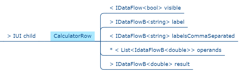
The implementation of CalculatorRow was done with a diagram using the new Graphical ALA tool which was shown earlier.
When you implement an abstraction by an internal diagram, there needs to be some extra code to wire from the ports (shown in the template above) to the internal wiring. I found this code quite tricky the first time and it took me a while. But there is a pattern to it. The new tool will be able to automatically generate this code as well, but for now I did it by hand.
I tested the completed CalculatorRow abstraction by making an application that uses it twice:
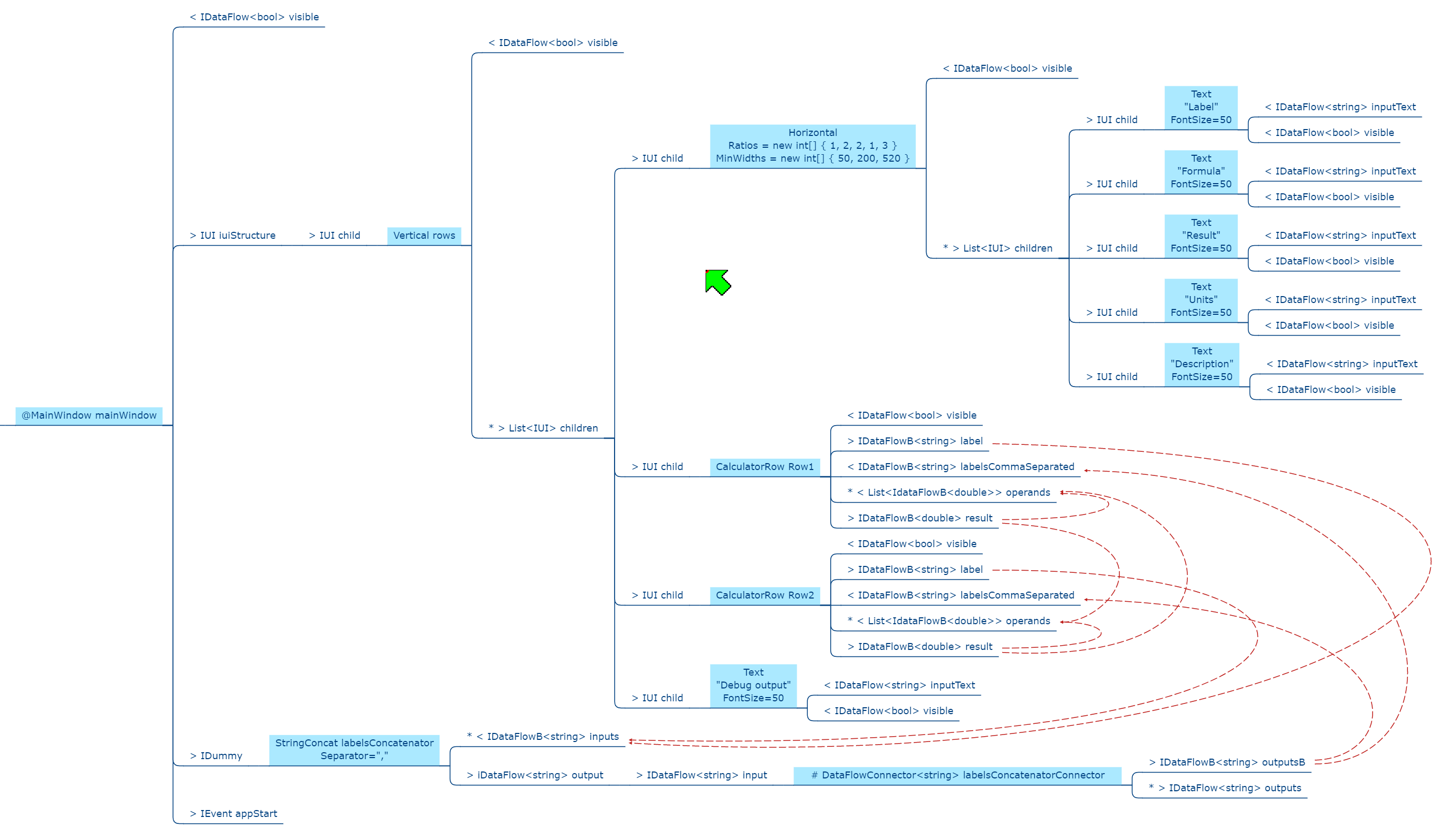
Because this test calculator has only two rows we can directly compare it with the 2-row calculator above and see how the two rows are now represented by two instances of this new CalculatorRow abstraction. However we are still not there to building a calculator with 10 rows. If we were to instantiate CalculatorRow 10 times, it would need 100 wirings in Xmind to connect all ten results to every CalculatorRow’s operands input. Having thought the 36 wirings of the 6 row calculator was nuts, there was no way I was going to do 100 of them by hand.
So the next step was to invent a domain abstraction called 'Multiple'.
What 'Multiple' does is you instantiate it in your application and configure it with the number you want. In this case N:10. Multiple has a port called factory which uses a new interface called IFactory. Then what you do is add a small Factory class inside any abstraction that you want multiple instances of. In this case we want multiple instances of CalculatorRow, so I added a small class to that abstraction called CalculatorRowFactory. CalculatorRowFactory implements IFactory (which resides in the Programming Paradigms layer). Multiple can now create many instances of the abstraction that is wired to it. But these instances now have to be wired into the rest of the wiring in the application diagram as needed. To accomplish that, multiple is configured with two methods. These methods, which are part of the application, know how to wire the new instances into the rest of the wiring.
Here is the Xmind template for Multiple:
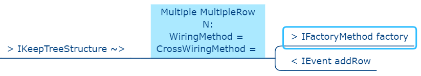
Using the new Multiple abstraction, we can now build a 10-row calculator. Here is the new diagram:
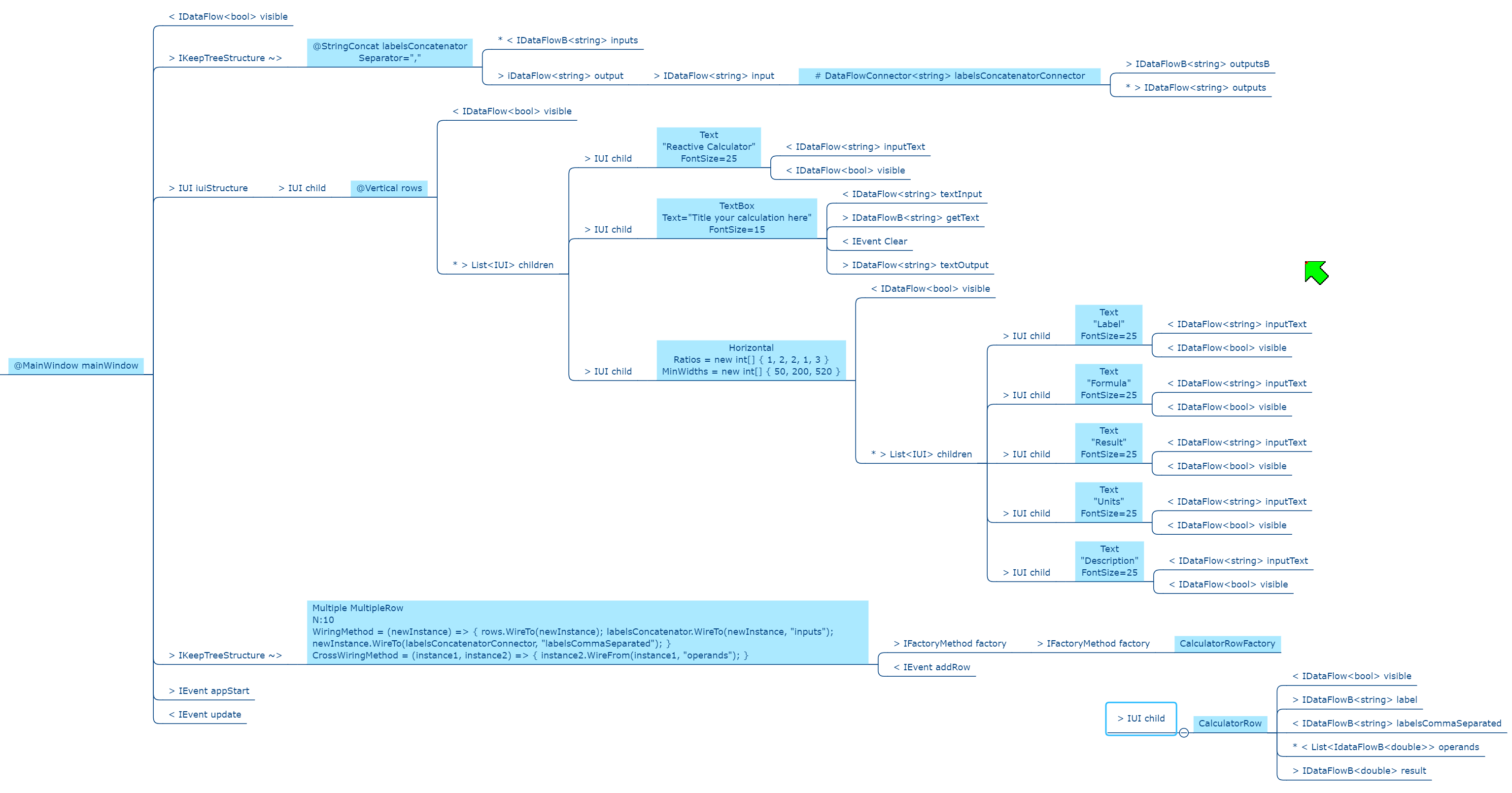
You can see inside the instance of Multiple that it is configured to make 10 of whatever is attached to its factory port. The CalculatorRow abstraction is shown next to the CalculatorRowFactory so you can see what it makes. You can see inside Multiple the two methods that Multiple calls when it makes a new instance. These methods are used to wire the CalculatorRow into the rest of the application wiring.
Getting to this point had taken another two Saturday mornings of work. It was mainly spent on thinking out the patterns for how the internal wiring inside CalculatorRow should get wired to CalculatorRows own border ports. Also in the initial attempt I had allowed temporal coupling to creep in between abstractions. It mattered whether the application wiring was done first. And if you let coupling creep in bugs will happen. The temporal coupling was resolved by making CalculatorRow not care whether or not the external wiring is done when it is instantiated.
5.8.6. Calculator with N rows
Wouldn’t it be cool if the calculator started with say 4 rows, and had a button for adding additional rows? You will notice that the Multiple abstraction template above has a port called addRow. It takes an IEvent. If it receives an event on that port at run-time, it will create another row and call the lambda wiring functions to get that row wired in.
Here is the calculator with the button added to the UI. This is the calculator from which the screen shot shown above was taken.
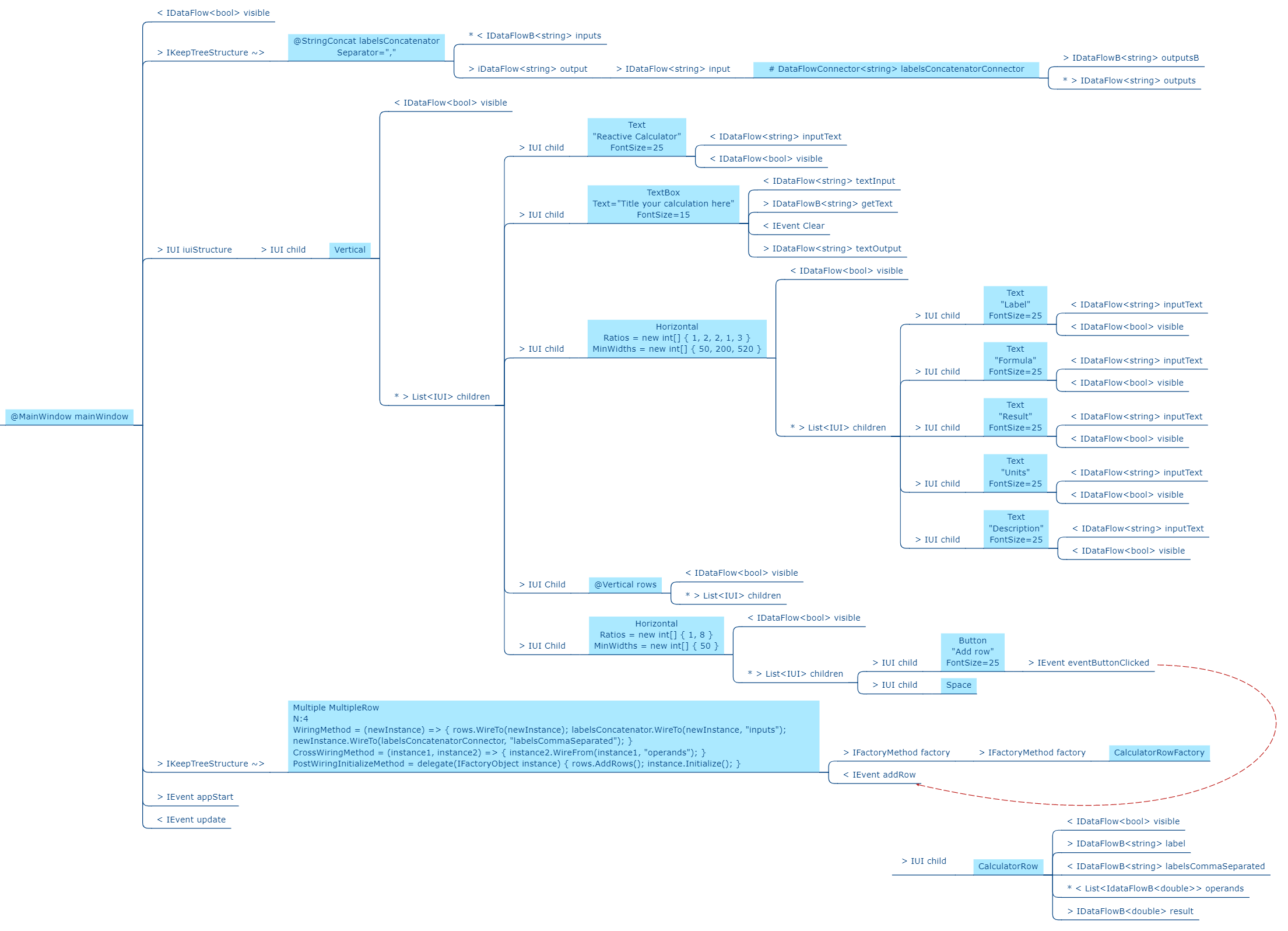
I wanted the Button to be at the bottom, so I added another instance of Vertical to act as the wiring point for new row to be attached to the UI. The output of the Button is another programming paradigm interface called an IEvent.
Here is the source code of IEvent:
namespace ProgrammingParadigms
{
    public interface IEvent
    {
        void Execute();
    }
}
Again, considering that this interface enables a whole programming paradigm, it is extremely simple and abstract, consisting of only a synchronous function call. It allows any objects that can produce events to be wired to any object that can receive an event. In the CalculatorNRows example, it allows a Button to be Wired to a Multiple. When the Button is pressed, Multiple creates a new row.
There is one major Programming Paradigm that we have not explained yet. It is the one that allows UI instances to be wired together. The meaning of wiring two UI objects together is that one contains the other. Here is the IUI interface that implements this programming paradigm.
using System.Windows;

namespace ProgrammingParadigms
{
    public interface IUI
    {
        UIElement GetWPFElement();
    }
}
The interface simply allows a containing UI instance to get the WPF (Windows Presentation Foundation) element from the contained UI instance it is wired to.
Making Multiple able to add rows to the calculator at runtime took yet another Saturday morning. But it was worth it to solve the challenge of learning how to change the wiring at run-time. The wiring diagram now statically describes how it dynamically changes itself.
That concludes the story of the development of the calculator using ALA. The full source code, and all the diagrams for every version along the way are in the Github project at https://github.com/johnspray74/ReactiveCalculator
6. Chapter six - ALA compared with:
In this chapter, our perspective is to compare ALA with existing programming paradigms, principles, styles, and patterns in common usage.
The idea is to understand ALA in terms of similarities and differences with something you may already understand.
Each existing programming paradigm, principle, style, or pattern generally takes a long time for the average developer to get used to and master. It then generally only makes an incremental improvement to software quality, if any. ALA is a reference architecture that combines the best elements of these existing programming paradigms, principles, styles, and patterns into one coherent idea that makes a big difference.
Some existing programming paradigms, principles, styles, or patterns are bad. The most prominent examples are the UML class diagram, the idea of 'decomposition' of a system (which includes all patterns like MVC), the idea that indirection is necessarily hard to trace, the idea of loose coupling, the idea of dependency management without distinguishing between good and bad dependencies, and the idea of layering patterns (sometimes called stacks) where the layers are driven by communication dependencies.
In this chapter we look at each of these good and bad patterns or styles in detail.
6.1. What are monads?
In chapter 3, we did a brief comparison of ALA and monads in which we assumed prior familiarity with monads. In this section we assume no familiarity with monads. So we start by explaining what monads are.
This section is necessarily long. Monads are notoriously one of the most difficult concept to understand in all of software engineering. But we will do it with tiny steps and a few examples built on real code.
We’ll do four examples of imperative code along with the refactored code that we call monads. Only by doing multiple examples will we get the underlying pattern of what monads are.
We will start by doing the refactoring from conventional code to monads in several small steps. At each step we will point out the advantages over the imperative code.
So let’s get started.
Often in imperative programming we find ourselves calling several functions in succession. What we are really doing is 'composing' functions. We would like to do this composing declaratively. By declaratively we mean that we would like to choose what functions and in what order, but not be concerned with any other details beyond that. It would allow us to think of the code as data flowing sequentially from operation to operation instead of imperative execution of statements.
In imperative style, top layer code that calls functions needs to handle data for the functions. For example, data returned by one function is often passed to the next. This often involves creating local variables to hold data temporarily. When we compose functions we want the output of one to be piped to the input of the next automatically without us having to do it explicitly. Looked at it in a different way, the functions' interfaces for input/output (the parameter and the return value) are exposed to the top layer when they don’t need to be. We would rather think of this input and output as separate interfaces or ports. When the top layer composes two functions, these ports are connected so that data is passed directly from one function to the next.
We can of curse achieve that using code like this:
int result = function3(function2(function1(42)));(In our sample code, we will use the number 42 as the input into the first function. That way we will be able to see where the source value being fed into the chain of functions is.)
Composing functions in this way is not scalable because of the increasing levels of nested brackets every time we want to add a new function to the chain.
To get a scalable version, we would write it like this instead:
int r1 = function1(42);
int r2 = function2(r1);
int result = function3(r2);
This form has the aforementioned disadvantage of handling the data that passes from function to function. Furthermore, those temporary local variables make the entire scope more complicated because anywhere in the scope can potentially use any variable. The variable can be immutable, but that doesn’t help much. Nevertheless, this is representative of the basic style that a lot of imperative code follows.
Let’s try to get to a style where we don’t need to handle that data ourselves, and we don’t have nested brackets. Let’s try using a function called 'Compose' to compose the functions:
int Compose(int x, Func<int,int> f)
{
    return (f(x));
}
So now we can compose the functions like this:
int result = Compose(Compose(Compose(42, function1), function2), function3);Well there doesn’t seem like there is any advantage to that. We got our nested brackets back, plus it looks even more complicated than our original bracketed code. But let’s persevere just a little longer with the idea of using a 'Compose' function, because it’s about to become really powerful.
First let’s make the Compose function an extension method by adding a this keyword:
static class ExtensionMethods
{
    public static int Compose(this int x, Func<int,int> f)
    {
        return f(x);
    }
}
Now we can compose the three functions this way:
int result = 42
    .Compose(function1)
    .Compose(function2)
    .Compose(function3);
This syntax is called fluent syntax. Fluent syntax is our first advantage of using a Compose function. We just solved the nested brackets problem, so the chain of functions is now scalable - we can easily add more functions to the chain. And, notice how the code using Compose is pure functional code. That’s because we got rid of all those local variables. The Compose function is starting to look useful.
The code is now a declarative dataflow programming paradigm instead of an imperative programming paradigm. We are just specifying what functions we want to compose in what order instead of imperatively calling them ourselves, and passing the data between them ourselves. It describes a flow of data rather than a flow of execution. You make think you know how this executes, but be careful, because you don’t know how Compose does the execution. And you will soon see that it can handle the execution in a variety of ways.
This is our second advantage of using a Compose function - it’s a pure dataflow programming paradigm where we are not concerned with how it executes.
The Compose function takes a function pointer (delegate in C#) as its parameter. If the functions being composed are specific to the application, i.e only ever used once, we can make them anonymous and put the function’s code directly into the Compose call:
int result = 42
    .Compose(delegate(int x){return x+1;)
    .Compose(delegate(int x){return x*10+1;})
    .Compose(delegate(int x){return 1/x;});
Doing it with delegates like that is somewhat verbose, so the next step is to change the syntax to lambda expressions.
int result = 42
    .Compose(x => x+1)
    .Compose(x => x*10+1)
    .Compose(x => 1/x);
So that’s our third advantage of using a Compose function. We can use lambda expressions right in the parameter of the Compose function instead of creating separate named functions.
6.1.1. Deferred execution
In the example so far, we assumed, based on the imperative code, that the Compose function directly and immediately calls the functions. When we compose the functions as a dataflow in the top layer, we assume that under the covers in the Compose function, the execution flow will be the same as the dataflow.
However, it is quite possible for the execution flow implemented in the compose function to work entirely differently from the dataflow. We can, for example, implement deferred execution, where the Compose function builds an executable structure which can be run later. This separation of how it executes from the declarative composition of the functions as a dataflow is our forth advantage of using a Compose function. It allows us to build Compose functions that use deferred execution.
The Compose function we had in the previous section evaluated the functions immediately and returned a result directly. Let’s write a deferred (or lazy) version of Compose. Instead of returning the actual result, this version will return a new function that represents the composed functions. This returned function can then be called later. Here is a deferred version of the Compose function:
static class ExtensionMethods
{
    static Func<int> Compose(this Func<int> source, Func<int,int> f)
    {
        return () => f(source());
    }
}
It’s the same as our previous Compose function except for the type of the first parameter and the return type. In the immediate execution version, the type of the first parameter to compose was an int, which comes from the execution of the previous function in the chain. And the return value was also an int. Now these two things are functions because we are not evaluating the functions as we go, we are composing the functions to return a new single function.
The () ⇒ syntax is a lambda expression for a function that takes no parameters. It creates a new function that calls the source function and then calls f.
What the Compose function returns is actually an object structure made up of delegates and closure objects created by the compiler:
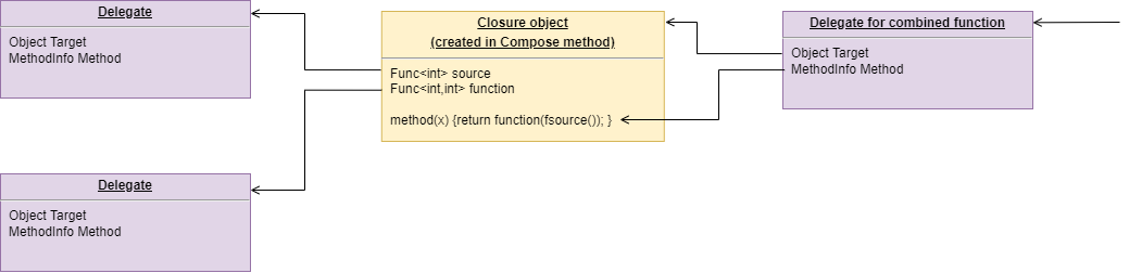
The purple boxes are C# delegates. Delegates can be thought of as a pointer to a method. Because the method is in an object, a delegate is actually a pointer to an object together with a reference to the method in that object’s class. Delegates themselves are objects. The delegate object has a pointer to another object (called Target) plus a reference to a method in that object (called MethodInfo).
The yellow box is a closure object. A closure is an object made from a compiler generated class with a single method. It can have fields which are references to variables in the local scope. In this case, the closure object has two fields, which are both delegates. The closure’s method calls the first delegate, and then calls the second delegate, passing the result returned by the first to the second. The structure is returned as a delegate that points to the method in the closure object.
The structure looks surprizingly complicated consisdering the code that generated it was just '() ⇒ f(source());' That doesn’t matter because its all generated by the compilier. I wanted to show it so we can see all the code for this deferred version of the compose function.
Now that we have a deferred version of our Compose function, we can use it like this:
Func<int> composedFunction = 42.ToFunc<int>
    .Compose(x => x+1)
    .Compose(x => 1000/x)
    .Compose(x => x*10+1);
That’s just the same as our previous top layer code, except that we show how we can get a function back which we can save to be executed later. It’s like we got a small program back.
When we want to execute the combined function, we can do it like this.
int result = composedFunction();We will usually prefer to build deferred versions of Compose functions, just because that gives us the versatility to execute them now or later, or even to execute them many times. In other words, Compose can build a program.
Note that the deferred version of Compose takes a function as its first parameter, not a number like 42. So we couldn’t pass 42 to it to start the chain. Instead we used another extension method called ToFunc to get a function that returns 42.
Deferred function composition generally returns a surprisingly large object structure containing delegate objects and closure objects all generated by the compiler. This is one reason why monads are so hard to understand. Here is what the object structure for the composedFunction above looks like:
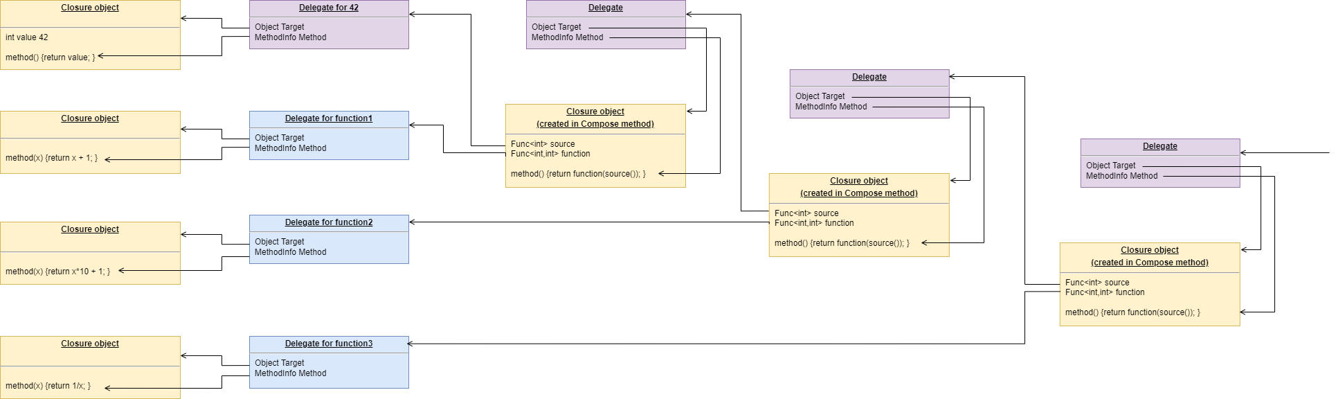
You can click on the diagram to see it enlarged. On the left side of the diagram you can see the four closure objects that implement the 42 and the three lambda expressions. Each of these closure objects has a delegate object that is used to reference it. Then there are three other closure objects that were created by the Compose function. These closures call the other closures via their delegates in the correct order. The entire structure is returned as a single delegate on the right hand side.
There is a fifth advantage to using a Compose function. This advantage is big, and is what allows us to finally call it a monad.
6.1.2. Composing functions that need logic between them
In imperative code we might typically need some extra code after every function call. A common example would be to check for errors returned by one function before calling the next function. If we have a compose function, we can put that extra code inside the Compose function instead. This refactoring is essentially what the monad pattern is.
We’ll give four examples of imperative code that needs some extra common logic after every function call. In each case, the functions we are composing are not returning a simple value that can be fed directly to the next function. They are returning something else, so in every case we need a little bit of extra logic to handle what the function returns before calling the next function.
It’s what this extra logic code does that distinguishes one monad from another.
6.1.3. Example 1
Composition of functions that can fail.
In this first example, we may need to allow for the fact that functions can throw an exception, or return null, or a Maybe object or even -1. For example, the function may be vulnerable to a divide by zero. In imperative code, we would commonly have to add if statements or try statements so that we don’t call the rest of the functions in the chain when something goes wrong. That will likely create nesting, arrrgh.
In C code, returning -1 is often used for this purpose, so let’s use that for our first example just because it’s so simple. Here is the imperative code:
// procedural composition of functions that can return -1 or null

int result1 = function1(42);
if (result1 != -1)
{
    int result2 = function2(result1)
    if (result2 != -1)
    {
        int result3 = function3(result2);
        if (result3 != -1)
        {
            DoSomething(result3);
        }
    }
}
// fall through means something returned -1
Note that, even though we are using intermediate variables, we got our nasty nesting back. Let’s see how we do that the monad way by refactoring the if statements into the Compose function:
The MinusOne monad
We simply factor out the if statements into the Compose function. When we create actual monads, we will name the composing function "Bind" instead of "Compose":
Application layer code
int result = 42
    .Bind(x => x+1)
    .Bind(x => x==0 ? -1 : 1000/x)
    .Bind(x = x*10+1);
Note that this looks almost identical to the way we composed these functions previously. That’s because our aim in the top layer is to just compose the functions, and nothing else.
One difference is that we have renamed Compose to Bind. That’s because Bind is the common name used for the Compose function in the monad world.
The only other difference is that the lambda expressions are now allowed to return -1 to indicate failure and the whole thing still works. We have done this in the second lambda expression. If any of the composed lambda expressions returns -1, then the rest of the lambda expressions are skipped, and the final result is minus one.
Now let’s see how that refactoring was done. Here is the Bind function:
Monad layer code
static class ExtensionMethods
{

    public static int Bind(this int source, Func<int, int> function)
    {
        return source == -1 ? -1 : function(source);
    }
}
You can see that if any function in the chain returns -1, the rest of the functions are skipped and the final result is -1.
That’s a pretty straightforward refactoring, and with it we have our first example of a monad.
Note that this Bind function does immediate execution. We will do the deferred version soon.
(Most of the code snippets in this section are demonstrated by small executable projects on Github here: https://github.com/johnspray74. The project names are MaybeMonad, IEnumerableMonad, and ContinuationMonad.)
To really 'get' monads, all we need is more examples of this type of refactoring.
6.1.4. Example 2
Composition of functions that return many values.
We may have functions that return many values, such as an array, a list, an IEnumerable or an IObservable. We then want to feed all the individual values into the next function, which will in turn return multiple values, and then recombine all the values nto a single array or list. In imperative code, we do this with nested for statements. For example, the function may be given customers one at a time and returns a list of their orders, which we want to join back into a single list of orders.
// imparative composition of functions that return a list

var results1 = function1(42);
List<int> combinedList1 = new List<int>;
foreach(result1 in results1)
{
    var results2 = function2(result1)
    List<int> combinedList2 = new List<int>;
    foreach (result2 in results2)
    {
        var results3 = function3(result2)
        combinedList2.Append(results3);
    }
    combinedList1.Append(combinedList2);
}
List<int> result = combinedList1;
Again note the nested levels of brackets and indenting for every foreach.
The List monad
We simply factor out the code for the foreachs into a new Bind function:
Application layer code
var result = List<int> result = new List<int>(){ 0 }
    .Bind(function1)
    .Bind(function2)
    .Bind(function3);
The functions each return a list. So as we Bind each new function, the number of items in the list multiplies up. Here is the same application using lambda expressions instead of named functions:
var result = new List<int> { 0 }
    .Bind(x => new List<int> { x * 10 + 1, x * 10 + 2, x * 10 + 3 })
    .Bind(x => new List<int> { x * 10 + 1, x * 10 + 2, x * 10 + 3 })
    .Bind(x => new List<int> { x * 10 + 1, x * 10 + 2, x * 10 + 3 });
Because we compose three functions, and each returns a list of three items, the result list at the end will contain 27 items. The output is:
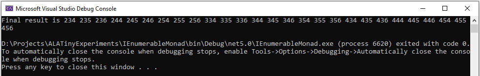
Here is the Bind function for the List monad:
static class ExtensionMethods
{
    public static List<U> Bind<T, U>(this List<T> source, Func<T, List<U>> function)
    {
        List<U> output = new List<U>();
        foreach (T t in source)
        {
            var List<U> functionOutput = function(t);
            output.AddRange(functionOutput);
        }
        return output;
    }
}}
For this monad, Bind will receive a list as its input. It will feed all the values one by one to the function. Each call of the function will return a list. Bind appends all the lists together and returns the combined list.
Let’s say the List<T> input were a list of students. Bind uses a for loop to get all the students one at a time. It passes each student to the function. Each call of the function returns a List<U>. Let’s say this is a list of courses for the student. The bind function then joins all the separate course lists together to make a single list of courses of type List<U>, which it returns.
Once again, the Bind function we gave above is the immediate version. We will soon do a deferred version, which uses IEnumerable<T> instead of List<T>.
6.1.5. Example 3
Composition of asynchronous functions.
The functions that we want to compose may contain delays, or they may wait for input or output, or they may wait for processing occurring on a different thread or processor. In other words, the functions may be asynchronous - they will return a result later, not immediately.
Because these type of function don’t return a value immediately, we can’t write an immediate execution monad. But we can still write a defered execution monad - a BInd function that will combine asynchronous functions, and return an asynchronous function.
There are different estanblished ways to implement asynchronous functions. The oldest is the callback. The function receives a callback function as an extra parameter. When the result is ready later, the callback function will be called to pass back the result.
More recently, asynchronous functions are implemented by returning a Task or future object. For our purposes here, a Task or future object are the same thing. They are an object that will have a result placed into it at a later time.
Here is the imperative version of the application layer code that composes functions that use callbacks. The common logic between the functions, function1, function2, and WriteLine is to create a callback function to be passed to the next, which is done using lambda functions:
static void ComposedFunction()
{
    function1(42, result =>
        {
            function2(result, result2 =>
                {
                    Console.WriteLine($"Final result is {result2}.");
                }
            );
        }
    );
}
Here is the imperative version of the application layer code that composes functions that return future objects. The common logic between the functions is to put a continuation function into the future object that was returned by the previous function:
static void ComposedFunction()
{
    function1(42)
    .ContinueWith(task1 =>
    {
        function2(task1.Result)
        .ContinueWith(task2 =>
        {
            Console.WriteLine($"Final result is {task2.Result}.");
        });
    });
}
In either case, notice the nasty indenting for every function we want to compose. In this case we could eliminate the indenting by using Unwrap() like this:
static void ComposedFunction()
{
    function1(42)
    .ContinueWith(task => function2(task.Result))
    .Unwrap()
    .ContinueWith(task =>
    {
        Console.WriteLine($"Final result is {task.Result}.");
    });
}
But I want to show how monads simplify this even further.
(Note that both versions require lambda expressions (for example, the lambda expression starting with 'task1 ⇒" ). In the first implementation above, the lambda expression is an Action. In the second implementation the lambda expression is a function. So they are two different overloads of ContinueWith. In the second implementation, the lambda function returns the type returned by the function, which is a Task<T>. So ContinueWith returns Task<Task<T>>. The Unwrap discards the outer Task.)
Of course, async/await also simplifies this particular example, but I want to show how monads can do it first.
The Task monad
For the Task monad, we simply factor out the ContinueWith logic into the Bind function. We can then use the Bind function like this in our top layer application code:
// monad composition of functions that return Task objects

Task<int> CombinedFunction =
    42.ToTask()
    .Bind(function1)
    .Bind(function2)
    .Bind(function3);
The value that Bind takes and returns is Task<T>. So the starting value, 42, has to be converted to a Task<T> first before it can be passed to the first Bind. That’s the purpose of the ToTask extension method.
Now let’s write the Bind function for the Task<T> monad. There is a way of using the compiler to cheat to implement the Bind function:
public static async Task<U> Bind<T, U>(this Task<T> source, Func<T, Task<U>> function)
{
    return await function(await source);
}
The async/await feature is indeed powerful, but our purpose is to see how Bind is a refactoring of the original imperative code. So here is the version that uses ContinueWith instead of async/await.
public static Task<U> Bind<T, U>(this Task<T> source, Func<T, Task<U>> function)
{
    var tcs = new TaskCompletionSource<U>();

    source.ContinueWith(
        (t) => function(t.Result).ContinueWith(
            (t) => tcs.SetResult(t.Result)
        )
    );
    return tcs.Task;
}
The Bind function is passed a Task<T> that will contain the input in the future. It immediately creates a new Task<U> to return. It actually creates a TaskCompletionSource object, which contains a Task. The TaskCompletionSource object just provides a method for putting the value into the Task when it is ready later. A closure object is created for the first lambda expression and a delegate object is created to call that. The ContinueWith attaches this delegate to the source Task<T> as a (callback) Action. The Task<> that is returned by ContinueWith is discarded.
This is how the code works at runtime. When the source Task<T> produces a result, the first lambda expression will run. When it does, it receives the Task<T>, extracts the actual result from it, and passes it to the function. The function immediately returns a Task<U> (a different Task<U> from the one created earlier). When the Task<U> produces a result, the second lambda is called. It extracts the actual result from the Task<U> and puts it into the original Task<U> via the TaskCompletionSource object.
The Bind function can also be written using Unwrap, which eliminates the need for the TaskCompletionSource:
public static Task<U> Bind<T, U>(this Task<T> source, Func<T, Task<U>> function)
{
    source.ContinueWith((t) => function(t.Result)).Unwrap();
}
When the lambda expression runs, it returns the Task<U> that is returned by the function, so the ContinueWith itself returns a Task<Task<U>>. The Unwrap discards the outer Task<>, leaving the Task<U> that is returned by the Bind function.
The async/await version generally runs everything on the same thread by default, which is great, but this is not the case for the ContinueWith version unfortunately. The example code on Github https://github.com/johnspray74/ContinuationMonad shows a console application that passes a TaskScheduler.FromCurrentSynchronizationContext() parameter to the ContinueWiths so that everything runs on the Console UI thread. That thread is never blocked.
The functions that can be composed using this Bind function must return synchronously with a Task object, but can take as long as they want to put a value into the Task. In the examples below, we will use one function with a delay, and one that does I/O. Another case is a function that will do CPU bound work on another thread.
For completeness, here are two example functions we can use to compose applications. These two function could be used in the application code that we did earlier:
    private static Task<int> function1(int x)
    {
        return Task.Delay(3000).ContinueWith(_ => x + 2);
    }
private static Task<int> function2(int x)
{
Console.WriteLine($"Value is {x}. Please enter a number to be added.");
string line = null;
return Task.Factory.StartNew(() => line = Console.ReadLine())
.ContinueWith(_ => x + int.Parse(line));
}The Task<T> monad was pretty heavy. We had to cover it because it’s one of the most important and most useful monads. But don’t worry if you didn’t get all the details of how those implementations of the Bind functions worked. The important point that we could write a Bind function that allowed us to compose asynchronous functions, functions that return a future rather than an immediate return value.
Now for our forth example, let’s do something much ligher.
6.1.6. Example 4
Let’s compose functions that return angles.
The three examples of monads that we did so far, the MinusOne monad, the List monad, and the Task monad are common monads in the industry. (Well, not the MinusOne monad, I made that one up, but the industry version of that is the Maybe monad, which we shall switch to when we look at deferred versions.)
For our last example, I wanted to do something custom, just to show that you really can create a monad to handle any type of intermediate logic you want between the functions you are composing. As long as we are always doing the same logic between all functions we compose, we can refactor that common logic into a Bind function.
Let’s say we always want to do modulo 360 arithmetic. And let’s throw in a total rotations counter as well, which we want to pass through the chain. Here is some imperative code:
// procedural composition of functions that can return angles

int rotations = 0;
int result1 = function1(42)
rotations += result1 / 360;
result1 = result1 mod 360;
int result2 = function2(result1)
rotations += result2 / 360;
result2 = result2 mod 360;
int result3 = function3(result2)
rotations += result3 / 360;
result3 = result3 mod 360;
The Mod360 monad
This is not strictly speaking a monad because the function doesn’t return the chaining interface type. That’s because in this case the function didn’t need to know anything about the rotations. However it still shows how the monad pattern can refactor arbitrary common code between composed functions.
Here is top layer application code to compose some functions handle angles. The second value in the Tuple is the number of rotations, which we initialize to 0.
Application layer code
Tuple<int,int> result = new Tuple(42,0)
    .Bind(function1)
    .Bind(function2)
    .Bind(function3);
Here is the Bind function:
public static Tuple<int,int> Bind<T, U>(this Tuple<int,int> source, Func<int, int> function)
{
    int result = function(source.Item1);  // call the function
    return new Tuple<int,int> (
        result mod 360,   // normalize the angle
        source.item2 + result/360);   // count rotations
}
This time Bind takes a Tuple and returns a Tuple. The Tuple contains the angle between 0 and 359 and the rotations. Bind will do the mod 360 on the result returned by the function, and add any whole rotations. It returns a new Tuple with those two values in it.
Note that it was easy to get the starting 42 value into the Tuple needed by the Bind function by simply using 'new Tuple(42,0)'. So in this case we didn’t need something like a ToTuple extension method.
6.1.7. The monad pattern
In all 4 of the above examples, the refactoring follows a pattern, which I will call the monad pattern.
In each case, we were able to create a compose function (called Bind) that just composes functions in a declarative way. In each case we were able to refactor any common logic needed in the imperative code between function calls into the Bind function. That’s pretty much what we are about with monads, composing functions using a Bind function and putting any common logic that is needed between each function into the Bind function as well. It is that common logic that distiguishes different types of monads.
The Compose function is often called Bind, but can go by other names such as the symbol ==>. If the monad is the list monad or IEnumerable monad, it can be called flatmap or SelectMany. The most common monad you will come across is the IEnumerable monad, but many other types of monads are possible.
More formerly, a monad consists of three elements:
-
a Bind function
-
a type that the Bind function takes as its first parameter and returns. This type is often an interface, or something we can think of as an interface in a general sense. We will refer to it as the chaining interface from now on. The chaining interfaces for the four monads we have done so far were int, List, Task and Tuple<int,int>. But often the type will be an actual interface such as IEnumerable as we will see soon.
Because Bind both takes and returns the chaining interface, Bind calls can be chained with dot operators. That’s why I call it the chaining interface.
The chaining interface is used in a third place in the monad pattern. It is the return type for the functions that can be composed. Although both the functions and Bind return the same type of interface, The object returned by the composed function is necessarily the one that is returned by Bind.
-
a function to use at the start of a chain of bind functions to convert an ordinary value like 42 to the chaining interface type so that we can pass it to the very first Bind. In monad land, this function is sometimes called unit or return. For the four example monads we have done, we didn’t need a unit function except for the Task monad, for which we created a ToTask extension method as the unit function. However in the upcoming deferred monads, we will generally need such an extension method.
To see how monads compare with ALA, we now want to do deferred versions of our 4 examples. Actually the Task<T> monad is already deferred, so we will just do the other three examples.
For the minus_one example, we are going to switch to the IMaybe monad first, because that’s the generally used solution to composing functions that may return no value. Skip this if you are already familiar with the IMaybe concept, unless you are interested to see how the IMaybe monad and its Bind function works.
6.1.8. IMaybe monad
Composition of functions that can fail by returning IMaybe<T> or Nullable<T>.
Using minus one, as we did earlier to represent a 'no value', is not used outside the C world, and limits the data itself to positive integers. The more general solution in the monad world is the IMaybe<T> monad. It’s called IMaybe because maybe it contains a value, or maybe it doesn’t.
The IMaybe version of Bind is similar to the -1 version. However the chaining interface is IMaybe<T>. Bind takes an IMaybe interface and returns an IMaybe interface, and the functions that we compose together also return an IMaybe interface.
We will have two classes that implement IMaybe. They are called Something and Nothing.
Here is example top layer application code composing functions that return IMaybe.
Application layer code
IMaybe<double> combinedFunctions = 42.ToMaybe()
    .Bind(x => new Something<int>(x+1))
    .Bind(x => x==0 ? new Nothing<double>() : new Something<double>((double)1/x) )
    .Bind(x => new Something<int>(x*10+1));
Something and Nothing are classes that implement IMaybe<T>, which we provide below for completeness.
The Bind function wont call the lambda expression if the result from the Bind is Nothing. But if the result from the previous Bind is Something, it takes the value out and gives it to the lambda function.
The Bind function takes an IMaybe as a parameter and returns an IMaybe. Notice that we need to convert the starting value, 42, to an IMaybe. That’s because the first Bind in the chain must have an IMaybe. To be a monad, we generally need to supply this method which is always used at the start of a chain of Binds.
Here is the IMaybe interface:
public interface IMaybe<T>
{
    bool HasValue { get; }
    T Value { get; }
}
IMaybe consists of two getters, one called HasValue() that returns a bool to find out if a value is there, and the other called Value to get the actual value out if there is one.
You would normally use HasValue first and only if it returns true would you use Value. HasValue is analogous to the MoveNext method in the IEnumerator interface, which you also have to call first before retrieving a value. We will need two classes that implement IMaybe, one to represent a nothing, and one to represent something:
Monad layer code
public class Nothing<T> : IMaybe<T>
{
    bool IMaybe<T>.HasValue { get => false; }
    T IMaybe<T>.Value { get { throw new Exception("No value"); } }
}


public class Something<T> : IMaybe<T>
{
    private T value;

    public Something(T value) { this.value = value; }

    bool IMaybe<T>.HasValue { get => true; }
    T IMaybe<T>.Value { get => value; }
}
The Bind function uses its input IMaybe<T> to see if there is a value present or not. If there is nothing it doesn’t call the function. It just returns a new IMaybe<U> implemented by a Nothing object. If there is a value, it gets the value and passes it to the function. Then Bind returns the IMaybe returned by the function. Here is the ToMaybe and Bind functions:
Monad layer code
static class ExtensionMethods
{
    public static IMaybe<T> ToMaybe<T>(this T value)
    {
        return new Something<T>(value);
    }


    public static IMaybe<U> Bind<T, U>(this IMaybe<T> source, Func<T, IMaybe<U>> function)
    {
        return source.HasValue ? function(source.Value) : new Nothing<U>();
    }
}
6.1.9. Deferred monad versions
All the monads we have done so far (except for the Task monad), were immediate or eager versions of the monads. This means that the Bind function calls the composed functions itself and passes the results(s) to the next function. We did the immediate versions because they are so simple.
However, we want to do deferred versions of all these monads because they are more versatile, and they create an object structure that is returned for later execution. We want to compare this object structure with the way ALA also creates an object structure composed of domain abstractions.
With deferred monads, we can do either pull versions or push versions.
For the pull version, we keep a reference to the last object in the structure. We call a method in that object when we want the result. That call pulls the data through the chain of objects. For the push version, we will keep a reference to the first object in the chain. When we want a result we will tell the first object to start, and the result will pop out of the other end.
In ALA, we generally default to programming paradigms that use pushing. To compare monads with ALA, we will therefore want to understand the push variations of the monads. However, pull monads are more common in the monad world. So we will do both. It gets pretty interesting to see the differences between the two in terms of how everything works in the code.
The implemtation code for each of the deferred versions will obviously be a little more complicated than the immediate versions of these monads. It will involve using objects to build a structure that can be returned for deferred execution. However, for completeness, I have not shied away from including all the code for the three monad examples. I have done this for both pull and push versions. It’s not necessary to read or understand all the code. But when you want to know exactly how something works, at least the code is there along with notes to explain it. I also include object diagrams explaining the object structure that is created beneath the covers by the Bind code.
6.1.10. Forcing execution of a deferred monad
Once you have written top layer application code for composing functions using a deferred monad, you may be wondering how you would execute the returned structure of objects to get he actual value. Well, given an object, s, that was returned by the monad expression, here are examples of the ways of forcing it to execute for various types of common monads:
if (s.HasValue) { use s.Value }      // maybe monad, calling HasValue causes eveluation
s.ToList()                           // IEnumerable
foreach (var value in s) {...}       // IEnumerable
s.Subscribe((x)=>{....})             // IObservable (push version of IEnumerable)
s.Result                             // Task (blocking version)
await s                              // Task (non blocking version)
use r.Item0, use r.Item1             // tuple. Accessing either Item cause evaluation
6.1.11. IMaybe monad (deferred, pull version)
We will write a deferred version of Bind that composes functions that can fail by returning IMaybe<T> or Nullable<T>. It is deferred, so it returns an object that implements IMaybe in a way that will evaluate the result when the Value is required.
Here is top layer code to use the deferred/pull implementation of the maybe monad.
IMaybe<double> objectStructure = 42.ToMaybe()
    .Bind(x => new MaybeSomething<int>(x+1))
    .Bind(x => x==0 ? new MaybeNothing<double>() : new MaybeSomething<double>((double)1/x) )
    .Bind(x => new MaybeSomething<int>(x*10+1));
It looks the same as the immediate version. But it returns an IMaybe that’s implemented by a large object structure instead of returning one of the two concrete IMaybe value objects.
First we define the IMaybe interface, which is the same as for the immediate version above. The MaybeNothing and MaybeSomething classes are also the same as before. Here they are again.
    public interface IMaybe<T>
    {
        bool HasValue { get; }
        T Value { get; }
    }

    public class MaybeSomething<T> : IMaybe<T>
    {
        T value;

        public MaybeSomething(T value) { this.value = value; }

        bool IMaybe<T>.HasValue { get => true; }
        T IMaybe<T>.Value { get => value; }
    }


    public class MaybeNothing<T> : IMaybe<T>
    {
        bool IMaybe<T>.HasValue { get => false; }
        T IMaybe<T>.Value { get { throw new Exception("No value"); } }
    }
The Bind function is different as it must build a structure that can be run later.
namespace Monad.MaybeDeferredPull
{
    static class ExtensionMethods
    {
        public static IMaybe<T> ToMaybe<T>(this T value)
        {
            return new MaybeSomething<T>(value);
        }

        public static IMaybe<U> Bind<T, U>(this IMaybe<T> source, Func<T, IMaybe<U>> function)
        {
            return new Maybe<T, U>(source, function);
        }
    }
As you can see, Bind simply instantiates new class called "Maybe" that implements IMaybe, which will do all the work at runtime.
namespace Monad.MaybeDeferredPull
{
    class Maybe<T, U> : IMaybe<U>
    {
        // implement the constructor, which receives the Action function
        private Func<T, IMaybe<U>> function;
        private IMaybe<T> source;
        private IMaybe<U> result; // null if we haven't evaluated yet

        public Maybe(IMaybe<T> source, Func<T, IMaybe<U>> function) { this.source = source; this.function = function; }

        bool IMaybe<U>.HasValue
        { get
            {
                if (result == null)
                {
                    if (source.HasValue)
                    {
                        result = function(source.Value);
                    }
                    else
                    {
                        return false;
                    }
                }
                return result.HasValue;
            }
        }

        U IMaybe<U>.Value
        {
            get
            {
                if (result == null)
                {
                     result = function(source.Value);  // will throw exception if no value
                }
                return result.Value; // will throw exception if no value
            }
        }
    }
}
The code that runs later in the Maybe class is the HasValue and Value getters. They do all the work.
This diagram shows the resulting structure from our little bit of application code above:
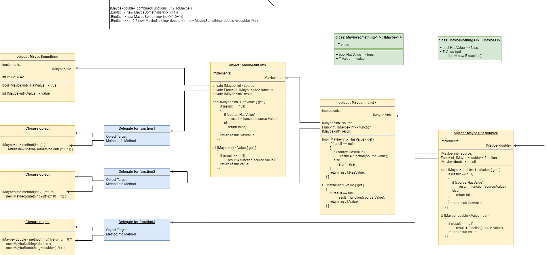
Because this is a pull implementation of the monad, the references go in the opposite direction of the dataflow - from destination to source or from right to left. When you want to run the combined function, you pull the value from the right end.
6.1.12. IMaybe monad (deferred, push version)
Having done the deferred pull version, we will now do the deferred push version, which has an interesting analogy with the IObservable.
Here is the top layer code, which in this case returns a IMaybeObservable.
IMaybeObservable<int> result = 42.ToMaybe()
    .Bind(function1)
    .Bind(function2)
    .Bind(function3);
I’ve purposely left the lambda expressions out for now. Well get back to them in a minute.
For the push version we need two interfaces. One, which we will call IMaybeObservable<T>, is the chaining interface that Bind takes and returns. The other, which we will call IMaybeObserver is for doing the actual pushing of data at runtime. The two interfaces work in opposite directions. That is IMaybeObservable<T> is always implemented by the previous object in the chain . IMaybeObserver is always implemented by the next object in the chain.
Here are the two interfaces:
    public interface IMaybeObservable<T>
    {
        void Subscribe(IMaybeObserver<T> observer);
    }
public interface IMaybeObserver<T>
{
void NoValue();
void Value(T value);
}That IMaybeObservable<T> implementation may at first seem a little strange. It has no way of getting the value out. That’s because we are implementing a push style monad. The IMaybeObservable<T> interface is used by Bind only to get a reference to the previous object in the chain. It then gives the previous object a reference to it’s next object, which the previous object will use to push the data. This second reference will use an interface called IMaybeObserver. And yes, these two interfaces are exactly analogous to the IObservable and IObserver interfaces in reactive extensions.
IMaybeObservable<T> is used by the next object in the chain.
The IMaybeObserver interface is used by the pervious object. (We could have chosen to use C# style events (observer pattern) instead of using IMaybeObserver, but it’s easier to do it exactly the same way as IObservable and IObserver).
Note that the IMaybeObserver interface’s methods are actions. They don’t pull a value like in the pull version we did of this monad, they push. I am tempted to rename them PushValue and PushNoValue to make this obvious everywhere that Value and NoValue are used.
Normally with monads, the type that the composable functions return would be the same as the chaining interface. So all functions that are composable by this monad should return IMaybeObservable, like this type:
Func<T, IMaybeObservable<U>>
Having all your functions return an IMaybeObservable would certainly work, but the functions would be a little complicated. They would all have to create an object that implements the IMaybeObservable interface to return. It would be far simpler if the functions were passed an IMaybeObserver instead of returning an IMaybeIObservable. So they would have this form:
Action<T, IMaybeObserver<U>>
Now when the functions run, they don’t need to create an object, they just directly push the result out via the IMaybeObserver<U>> interface that was passed to them. So that’s what we will do in our example. It’s a more loose interpretation of the definition of monad, but it’s just more sensible to do it that way.
Note that the IMaybeObserver interface (listed above) could have been written with a single method like this:
void Push(IMaybe<T> data)
However, to make it as easy as possible for the composable functions to use the interface (not have to create a Something or Nothing object), I have changed the interface to be two methods:
void NoValue(); void Value(T value);
So now we can write the application layer code using simple lambda expression syntax:
IMaybeObservable<double> combinedFunction = 42.ToMaybe();
    combinedFunction
    .Bind((x,ob) => ob.Value(x+1))
    .Bind((x,ob) => { if (x==0) ob.NoValue(); else ob.Value((double)1/x); } )
    .Bind((x,ob) => ob.Value(x*10+1));

    combinedFunction.Start();
Note that we keep a reference to the source of the chain, not the end. That is the object returned by ToMaybe(). This object has a Run method. The structure starts executing when the Run method is called. This is a departure from the way IObservable and IObserver work. With IObservable, the Subscribe method both wires the IObserver in the opposite direction, and tells the source to start. So even though it’s suppossedly a push style, execution is started from the destination end, which makes it look like a pull style. This loses some of the advantages of using a push style, for example, when it is the source that wants to initiate a push whenever the source changes, or when using asynchronous communication across a network. I really think the straightforward push system is conceptually purer and more useful. So that is what I have implemented.
Here are the ToMaybe and Bind functions for the IMaybe deferred push monad:
namespace Monad.MaybeDeferredPush
{
    static class ExtensionMethods
    {
        public static IMaybeObservable<T> ToMaybe<T>(this T value)
        {
            return new MaybeStart<T>(value);
        }

        public static IMaybeObservable<U> Bind<T, U>(this IMaybeObservable<T> source, Action<T, IMaybeObserver<U>> action) (1)
        {
            var maybe = new Maybe<T, U>(action);
            source.Subscribe(maybe);
            return maybe;
        }
    }

}| 1 | The Bind function just creates an object to do all the work at runtime. The object is defined by a class called Maybe (listed below). The Bind function takes an IMaybeObservable interface and returns that same interface. It composes Actions rather than functions. These actions take an IMaybeObserver. |
namespace Monad.MaybeDeferredPush
{

    class Maybe<T, U> : IMaybeObserver<T>, IMaybeObservable<U> (2)
    {
        private Action<T, IMaybeObserver<U>> action;

        public Maybe(Action<T, IMaybeObserver<U>> action) { this.action = action; }


        private List<IMaybeObserver<U>> subscribers = new List<IMaybeObserver<U>>(); (4)

        void IMaybeObservable<U>.Subscribe(IMaybeObserver<U> observer) (2)
        {
            subscribers.Add(observer);
        }

        void IMaybeObserver<T>.NoValue()
        {
            foreach (var subscriber in subscribers)
            {
                subscriber.NoValue();
            }
        }

        void IMaybeObserver<T>.Value(T value)
        {
            action(value, new ActionObserver<T, U>(this));
        }

        private class ActionObserver<T, U> : IMaybeObserver<U> (3)
        {
            private Maybe<T, U> outer;
            public ActionObserver(Maybe<T, U> outer) { this.outer = outer; }

            void IMaybeObserver<U>.NoValue()
            {
                foreach (var subscriber in outer.subscribers)
                {
                    subscriber.NoValue();
                }
            }

            void IMaybeObserver<U>.Value(U value)
            {
                foreach (var subscriber in outer.subscribers)
                {
                    subscriber.Value(value);
                }
            }
        }
    }


    class MaybeStart<T> : IMaybeObservable<T>
    {
        private T value;
        public ToMaybe(T value) { this.value = value; }

        private List<IMaybeObserver<T>> subscribers = new List<IMaybeObserver<T>>();
        void IMaybeObservabe<T>.Subscribe(IMaybeObserver<T> subscriber)
        {
            subscribers.Add(subscriber);
        }

        public void Run()
        {
            foreach (var subscriber in subscribers)
            {
                subscriber.Value(value);
            }
        }
}| 1 | The Maybe class implements both IMaybeObservable and IMaybeObserver. IMaybeObservable is only used by Bind. It’s Subscribe method wires the IMaybeObserver in the opposite direction. IMaybeObserver is the one that is used at runtime to push the data through. |
| 2 | Remember the 'composable functions' in the application layer are not Funcs but Actions that take a value and an IMaybeObserver<U>. So we need a class that implements IMaybeObserver so we can make observer objects to pass to the Actions when we call them at runtime. This class is implemented as an inner class called ActionObserver. |
| 3 | The wiring of Maybe supports fanout or multiple subscribers (just like the observer pattern). We will do it for all deferred push style monads. It is normal for push monads to support fan out, in other words many observers can be subscribed to the one observable. It is another advantage of push style monads over pull style monads. |
Here is an object diagram of the complete expression.
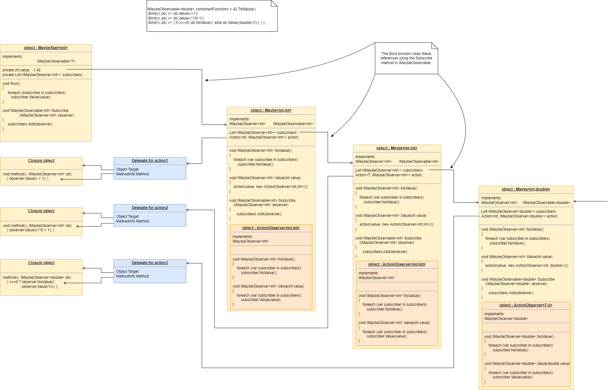
You can see that although using the IMaybe monad Bind function from the top layer to compose three functions is extremely simple, the structure of objects that is generated under the covers is relatively complicated. It’s no wonder that these monad things seem so hard to understand at first.
The references between the objects, which use IMaybeObserver, go in the same direction as the dataflow. IMaybeObservable is only used for wiring the structure up.
So far we have done deferred pull and deferred push implementations of the IMaybe monad. Now lets do the deferred verson of the List monad, the IEnumerable monad
6.1.13. IEnumerable monad
Composition of functions that return many values, in this case an IEnumerable.
The IEnumerable monad is the deferred version of the list monad we did earlier. The IEnumerable monad is the most commonly used monad, and is what LINQ is based on.
The Bind function for the IEnumerable monad is called SelectMany in C#. SelectMany is not used as often as Select. Select takes a simpler function that returns U instead of IEnumerable<U>, so it doesn’t expand the number of items, it just does a one-to-one mapping. While Select is used more often, it is the SelectMany function that makes it a Monad. Here in our example application we will use three SelectManys in a row. Each will expand in number by 3, so we will end up with an IEnumerable with 27 items in the end.
Here is example top layer code that composes functions that return IEnumerable
IEnumerable<int> result = 42.ToEnumerable()
    .SelectMany(function1)
    .SelectMany(function2)
    .SelectMany(function3);
Remember that for the IEnumerable monad, function1, function2, and function3 take a single value and return many values in the form of an IEnumerable.
In the immediate example above that returned lists, the lambda expressions looked like this:
var result = new[] { 0 }
    .Bind(x => new[] { x * 10 + 1, x * 10 + 2, x * 10 + 3 })
    .Bind(x => new[] { x * 10 + 1, x * 10 + 2, x * 10 + 3 })
    .Bind(x => new[] { x * 10 + 1, x * 10 + 2, x * 10 + 3 });
While this will run fine when using the IEnumerable version of Bind, it’s not really in the style of a deferred monad to create memory hungry arrays. So let’s write functions that will do the same job in a deferred way:
private static IEnumerable<int> MutiplyBy10AndAdd1Then2Then3(int x)
{
    yield return x * 10 + 1;
    yield return x * 10 + 2;
    yield return x * 10 + 3;
}
The yield return keyword causes the compiler to generate an IEnumerable object, which it returns. The IEnumerable object contains a state machine where each state executes code till it hits the next yield return statement.
Let’s just reuse that function three times in our composed function:
static void Application()
{
    var program = new[] { 0 }
    .Bind(MutiplyBy10AndAdd1Then2Then3)
    .Bind(MutiplyBy10AndAdd1Then2Then3)
    .Bind(MutiplyBy10AndAdd1Then2Then3);

    var result = program.ToList();  // now run the program
    Console.WriteLine($"Final result is {result.Select(x => x.ToString()).Join(" ")}");
}
The Bind function (SelectMany) for this type of monad takes an IEnumerable<T> and returns an IEnumerable<U>. The Bind function doesn’t use a for loop immediately as that would defeat the laziness. Instead the bind function uses an object that keeps state. Let’s call this object the output IEnumerable. The output IEnumerable knows how to use the source IEnumerable<T> to get the first value, which it gives to the function. The function returns an IEnumerable<U> which we will call the function return IEnumerable. The output IEnumerable then knows how to get the values from the function return IEnumerable<U> and return them one at a time. When it has exhausted all of them, the output IEnumerable<U> then gets the next value from the source IEnumerable<T>, and gives that to the function. The function again returns an IEnumerable<U>. This process continues until the source and function output IEnumerables are both exhausted.
In C#, the Bind function is really easy to write because the compiler can build an IEnumerable for you using the yield return syntax:
namespace Monad.Enumerable
{
    static class ExtensionMethods
    {
        public static IEnumerable<U> Bind<T, U>(this IEnumerable<T> source, Func<T, IEnumerable<U>> function)
        {
            foreach (var t in source)
            {
                var enumerator = function(t);
                foreach (var u in enumerator)
                {
                    yield return u;
                }
            }
        }
    }
}
Note that the code in the function does not run when this Bind function runs. The compiler sees the yield return and builds an object containing a state machine that implements IEnumerable<U>, and returns that.
Since our purpose is to show how the Bind function is a refactoring of imperative code, here is a version that doesn’t cheat by using the yield return syntax:
static class ExtensionMethods
{
    public static IEnumerable<U> Bind<T, U>(this IEnumerable<T> source, Func<T, IEnumerable<U>> function)
    {
        return new EnumerableMonad<T, U>(source, function);
    }
}
All Bind does is instantiate the class and return it. The class gets passed the source IEnumerable and the function. The class implements IEnumerable<U> for its output, which means it must be able to return an object implementing IEnumerator. The easiest way to do that is have the class implement IEnumerator<U> as well. Then the IEmumerable can just return 'this'.
class EnumerableMonad<T, U> : IEnumerator<U>, IEnumerable<U>
{
    private readonly IEnumerable<T> source;
    private readonly Func<T, IEnumerable<U>> function;

    public EnumerableMonad(IEnumerable<T> source, Func<T, IEnumerable<U>> function)
        { this.source = source; this.function = function; } (1)

    private IEnumerator<T> sourceEnumerator = null;

    IEnumerator<U> IEnumerable<U>.GetEnumerator()
    {
        sourceEnumerator = source.GetEnumerator();
        return (IEnumerator<U>)this;
    }

    IEnumerator IEnumerable.GetEnumerator()
    {
        sourceEnumerator = source.GetEnumerator();
        return this;
    }


    private IEnumerator<U> functionEnumerator = null;

    U IEnumerator<U>.Current => functionEnumerator.Current;

    object IEnumerator.Current => throw new NotImplementedException();

    void IDisposable.Dispose() { }

    bool IEnumerator.MoveNext() (2)
    {
        while (true)
        {
            if (functionEnumerator != null)
            {
                if (functionEnumerator.MoveNext())
                {
                    return true;
                }
            }

            if (sourceEnumerator.MoveNext())
            {
                functionEnumerator =
                    function(sourceEnumerator.Current).GetEnumerator();
            }
            else
            {
                return false;
            }
        }
    }

    void IEnumerator.Reset()
    {
        functionEnumerator = null;
        sourceEnumerator.Reset();
    }
}| 1 | The constructor is passed both the sourceIEnumerable and the function. It saves both of them in local variables. |
| 2 | The IEnumerator MoveNext method does all the work of the class at runtime. It is called by the next object in the chain. It gets the first element from the source, and feeds it to the function. Then it stores the Enumerator it gets from the function so it can use it in subsequent calls. Then it gets the first element from the function’s Enumerator and returns it. A while loop is necessary because when the Enumerator that is returned by the function runs out, it needs to go back and get the next element from the source and pass that to the function. |
The class is completely lazy, so it doesn’t even get the source IEnumerator from the source IEnumerable until the first call of MoveNext.
The two fields, sourceEnumerator, and functionEnumerator are the state. The first can have a state of null, which is the state before we got the first value.
The object diagram for the program again shows three objects wired in a chain from right to left:
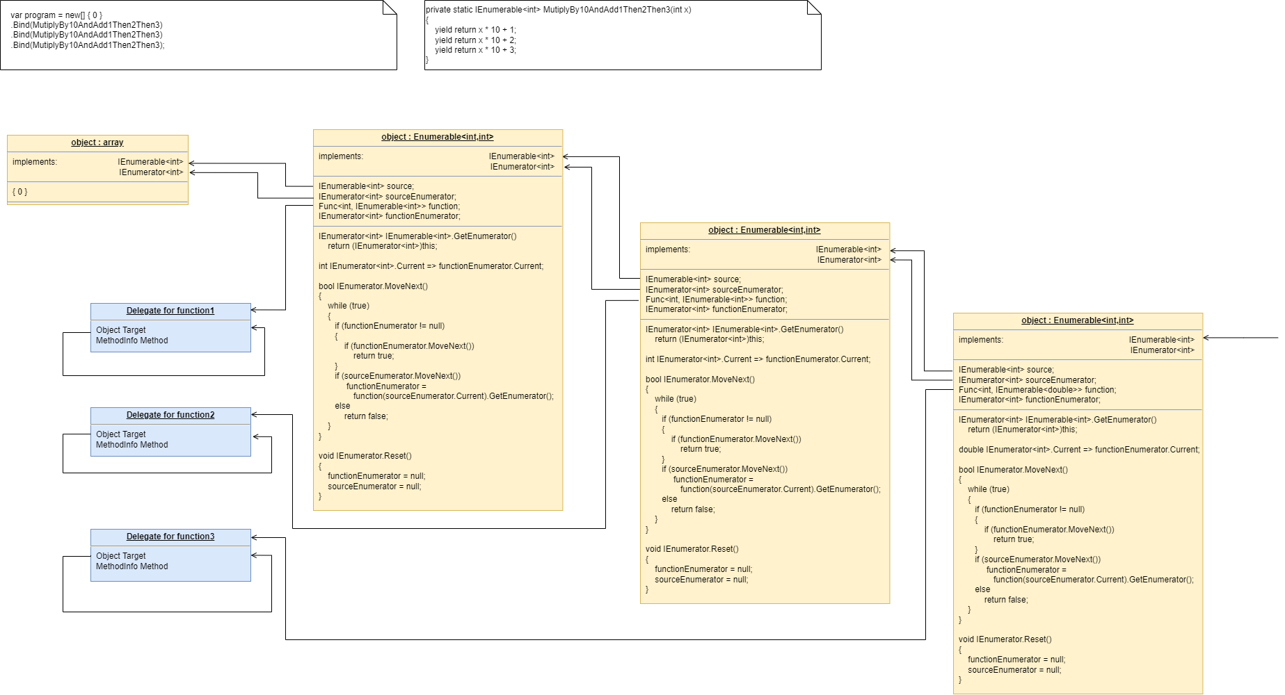
Bind just wires the IEnumerable interface. The IEnumerable GetEnumerator method then effectively wires the IEnumerator interface (in the same direction). So you might wonder if the IEnumerable interface could be considered redundant. We not just make Bind wire up the IEnumerator interfaces and dispensed with IEnumerable altogether? That would work, but I guess the reason IEnumerable exists is because IEnumerator is already implemented by many underlying library collections. When writing a new class that will support foreach, we need only provide a GetEnumerator method that simply returns the underlying collection instead of implementing the whole IEnumerator interface. However in our class above, this didn’t help because we had to implement the whole IEnumerator interface because we were recombining multiple collections.
6.1.14. IObservable monad
The IObservable monad is the push version of the IEnumerable monad, sort of.
Once the flow of data begins, it is indeed pushed (source to destination). The data is pushed using the IObserver interface. But with the IObservable IObserver pair of interfaces, it the destination that initiates the transfer. The destination uses the Subscribe method in the IObservable monad to register to observe the data. This Subscribing is also what initiates the transfer in the source. Once a transfer is completed, another transfer can usually be started by unsubscribing and resubscribing. When used in this way, IObservable is sort of a pull programming paradigm when you consider which end initiatiates the data transfer.
Some writers equate IObservable with "asynchronous". However, a pushing interface like IObserver can be either synchronous or asynchronous. Data flows from the source object by calling a method in the IObserver interface, called OnNext. That method can execute synchronously all the way to the destination end of the chain, or it can return at any point along the chain, and the data flow can resume from that point at a later time, which is what we refer to as asynchronous.
Pull communications can’t be asynchronous or broken up in time, at least not in a straight forward way. It either requires blocking the thread (we don’t want to go there) or using a Callback, or using a Task or future object (which we covered earlier). The IEnumerator interface, being a pull interface, can only work synchronously. With IEnumerator, the destination end pulls data by calling a method. The function must execute synchronously all the way to the source otherwise it would return without a result.
The ability of push style programming to be either synchronous or asynchronous is a good reason to default to using it. It is the reason ALA defaults to using push. Sometimes there are good reasons to use pull, but where it doesn’t matter, we prefer push. So it is worth looking at the IObservable monad for comparing with ALA, even though IEnumerable monads tend to be more common in practice, but only because they work well for database queries (pull data from the database). IObservable is the closest for comparison with the common ALA programming paradigms.
Unlike the IEnumerable/IEnumerator pair of interfaces which go in the same direction, the IObservable/IObserver interfaces go in opposite directions. The IObservable interface goes from destination to source whereas the IObserver interface goes from source to destination to carray the data.
In the context of monads, the IObservable interface, being in the direction of destination to source, is the one that is used by Bind. IObserable is then used to wire and initiate the IObserver interface in the opposite direction. This is exactly what we did earlier with the IMaybe push monad.
In the context of ALA, it is a disadvantage to combine the 'wiring' and the 'start transfer' in the same Subscribe method call. In ALA we keep these two things separate because we want the code for these two things to be in two separate places. The wiring code represents a user story and so goes in a user story abstraction in the top layer. We wire up the entire program first and then set it running. The starting of a data transfer is a run-time event. It originates in the same layer, for example, from a button domain abstraction that is wired to it. However, because this is the IObservable monad and not ALA, the Subscribe method will do both functions - the wiring of the observer and then starting a single data transfer.
Another thing we will do, like we did for the deferred/push version of the Maybe monad, is compose Actions instead of Funcs. When an Action is called at runtime, it will be passed an object that implements IObserver. The action will use the IObserver to output directly instead of having a function that retirns an IObservable. This greatly simplifies the code in the Actions, which is what we want because these Actions are application code. Instead the Bind function will take on extra work. It needs to create an IObserver object to pass to the actions.
If you look at the SelectMany in the reactive extensions library for C#, you will see that it takes a Func. But there are two overloads. In one, the Func returns an IObservable object as expected. For the other, it returns an IEnumerable. It’s a shame that the second overload doesn’t take an Action that takes an IObserver. That would have truly simplified things. Anyway that’s what we will do in our example here.
Here is an action to use in our example applicaton:
static void MutiplyBy10AndAdd1Then2Then3(int x, IObserver<int> observer)
{
    observer.OnNext(x * 10 + 1);
    observer.OnNext(x * 10 + 2);
    observer.OnNext(x * 10 + 3);
    observer.OnCompleted();
}
It takes a single integer as input and outputs a stream of three integers. The output goes to the IObserver that is also passed to the Action.
Here is our top layer application code.
static void Application()
{
Observable.Create<int>(
    observer => {
        observer.OnNext(0);
        observer.OnCompleted();
        return Disposable.Empty;
    })
    .Bind<int,int>(MutiplyBy10AndAdd1Then2Then3)
    .Bind<int,int>(MutiplyBy10AndAdd1Then2Then3)
    .Bind<int,int>(MutiplyBy10AndAdd1Then2Then3)
    .Subscribe((x) => Console.Write($"{x} "),
                (ex) => Console.Write($"Exception {ex}"),
                () => Console.Write("Complete")
                );
}
We start with a single integer with value zero. We conver it to IObservable using the reactive extensions Observable.Create method. Then we can use Bind on that to compose the action. We do that using the same action for all three times. Finally we send the output to the Console. We use an overload of Subscribe that creates a destination object.
Now let’s write the Monad’s bind function. As usual, C# (in this case the reactive extensions library) provides us with a shortcut way to implement Bind by using Observable.Create and Observer.Create. This shortcut method obscures the way the Bind function is a refactoring of the imperative code, which is our purpose. However, for reference, here is the shortcut version first:
static class ExtensionMethods
{

    public static IObservable<U> Bind<T, U>(this IObservable<T> source, Action<T, IObserver<U>> action)
    {
        return Observable.Create<U>(outputObserver => (1)
        {
            source.Subscribe( (2)
                x => { action(x, Observer.Create( (3)
                        value => outputObserver.OnNext(value), (4)
                        ex => outputObserver.OnError(ex), (4)
                        () => { } (4)
                    ));
                }, (5)
                ex => outputObserver.OnError(ex), (3)
                () => outputObserver.OnCompleted() (3)
            );
            return Disposable.Empty;
        });
    }
If you find this version hard to read, just skip forward to the next version.
| 1 | Bind must return an IObservable, so the first thing we do is create a new IObservable to be returned.
The Observable.Create method in the reactive extension library will create an object that implements IObservable. You pass it a Subscribe function. It does nothing more than create an object that implements IObservable, and uses the Subscribe method you gave it as the implementation of the IObservable. In this case we pass in a lambda (anonymous function) as the Subscribe method. Remember a Subscribe method is passed an IObserver, so that’s the 'outputObserver' part of the lambda expression. The lambda expression takes up the entire rest of the code starting from 'outputObserver ⇒'. |
| 2 | When the Subscribe lambda expression gets called at runtime, it must subscribe to the source. |
| 3 | In subscribing to the source, we supply three functions for the source to call, OnNext, OnError and OnCompleted. The OnError and OnCompleted are routed directly to the outputObserver. The OnNext is routed to the action. |
| 4 | The action must in turn be given an observer for it to output to. Observer.Create creates an object that implements IObserver. You provide the three functions, OnNext, OnError, and OnCompleted that the IObserver interface needs.
If the action outputs data it is passed directly to the outputObserver. If the action outputs an error, it too is passed directly to the outputObserver. But if the action outputs OnCompleted, it is discarded. This is ecause the monad must combine the streams from multiple calls of the action into a single stream. |
You may think we do not need the extra observer. Why not just pass outputObserver to the action like this:?
x => action(x, outputObserver);That would indeed correctly pass the multiple outputs of the action to the outputObserver. However, the action may call OnCompleted at the end of each of its sequences. If it does we need to intercept it and remove it because otherwise it will terminate the outputObservable sequence prematurely. This removal of the OnCompleted from the function’s output is effectively what 'flattens' the output.
Removing the OnCompleted call is the reason we use Observer.Create().
Now we do a version that does not use either Observable.Create or Observer.Create. Although the code is longer, this will be easier to understand since our purpose is to show how we can refactor the original imperative code. This shows more clearly that the Bind function works by instantiating an object that will do all the work at runtime, and then simply wires that object to the previous one.
public static IObservable<U> Bind<T, U>(this IObservable<T> source, Action<T, IObserver<U>> action)
{
    return new Observable<T, U>(source, action);
}
The bind function simply instantiates an object from an explicit class called Observer. This class is listed below.
private class Observable<T, U> : IObserver<T>, IObservable<U> (1)
{
    private readonly IObservable<T> source;
    private readonly Action<T, IObserver<U>> action;

    public Observable(IObservable<T> source, Action<T, IObserver<U>> action) { this.source = source; this.action = action; } (2)


    private IObserver<U> output;
    private InnerObserver<U> innerObserver;

    IDisposable IObservable<U>.Subscribe(IObserver<U> observer) (3)
    {
        output = observer;
        innerObserver = new InnerObserver<U>(output);
        source.Subscribe(this);
        return Disposable.Empty;
    }

    void IObserver<T>.OnCompleted() (4)
    {
        output.OnCompleted();
    }

    void IObserver<T>.OnError(Exception ex) (4)
    {
        output.OnError(ex);
    }

    void IObserver<T>.OnNext(T value) (5)
    {
        action(value, innerObserver);
    }

    // Observer that simply interceps OnCompleted
    private class InnerObserver<U> : IObserver<U> (6)
    {
        public Observable(IObserver<U> output) { this.output = output; }

        IObserver<U> output;

        void IObserver<U>.OnCompleted() { } // discard

        void IObserver<U>.OnError(Exception ex) { output.OnError(ex); }

        void IObserver<U>.OnNext(U value) { output.OnNext(value); }
    }
}| 1 | The objects of this class implement both IObserver and IObservable. IObserver allows the object to be used to subscribe to the source. IObservable allows the next object in the chain to subscribe to it. |
| 2 | The class’s constructor stores the source and the action. |
| 3 | The class’s Subscribe method saves the output observer. It also Subscribes this object to the source, which usually starts the transfer of data. |
| 4 | The OnCompleted and OnError methods, (which are called by the source) simply pass through to the output observer. |
| 5 | The OnNext method, (which is called by the source) calls the action, and passes it the InnerObserver object to output to. The InnerObserver passes OnNext and OnError through to the output, but discards any OnCompleted produced by the action. This discarding of OnCompleted from the action is what joins all the sequences produced by the calls to the action together. |
| 6 | The InnerObserver’s only function is to remove OnCompleted calls from the action getting to the output so that the sequences get joined. (Note: We could have used Observer.Create instead of having the InnerObserver class. However, we would have had to use Observer.Create in the OnNext method to get a new instance to pass to the action every time. This is because the observer object created by Observer.Create will stop working when it gets a OnCompleted.) The explicit InnerObserver class makes it a little clearer what is going on. |
6.1.15. Mod360 monad
Finally, let’s do a deferred version of the mod360 monad that we used as one of our original examples. You’ll remember that we had imperative code that was doing mod 360 after every function call. We already did a simple immediate version of the monad. Let’s skip the deferred/pull version and go straight to the deferred/push version.
Here is a suitable interface for the monad:
interface IMod360Observer
{
    void Push(Tuple<int,int> value);
}
Item0 in the Tuple is the angle, and Item1 in the tuple is the rotations.
And we will need a chaining interface for the Bind function to use:
interface IMod360Observable
{
    void Subscribe(IMod360Observer observer);
}
Here is the application example code using the monad:
Application layer code
var program = 42.ToMod360();
program.Bind(function1).Bind(function2).Bind(function3);

program.Run()
Here is the Bind function and ToMod360 function. Both use explicit classes to do the actual work.
Monad layer code
static class ExtensionMethods
{
    public static IMod360Observable ToMod360(this int value)
    {
        return new Mod360Start(value);
    }

    public static IMod360Observable Bind(this IMod360Observable source, Func<int,int> function)
    {
        var mod360 = new Mod360(function);
        source.Subscribe(mod360);
        return mod360;
    }
}
The Bind function just instantiates a Mod360 class, configures it with the function being composed, and wires it to the previous object using the Subscribe method of its observable interface. The Subscribe method effects wiring in the opposite direction using the observer interface, which is needed because it is a push monad.
The class that does the work for the Bind function is below. It implements IMod360Observer for use by the previous object, and IMod360Observable for use by the next object.
class Mod360 : IMod360Observer, IMod360Observable
{
    private Func<int,int> function;

    public Mod360(Func<int,int> function) { this.function = function; }


    private List<IMod360Observer> subscribers = new List<IMod360Observer>();

    void IMod360Observable.Subscribe(IMod360Observer observer)
    {
        subscribers.Add(observer);
    }


    void IMod360Observer.Push(Tuple<int,int> value)
    {
        int functonResult = function(value.Item1);
        Tuple<int,int> result = new Tuple<int,int> (
                functionResult mod 360,   // normalize the angle
                value.Item2 + functonResult/360) // count rotations
            );
        foreach (var subscriber in subscribers)
        {
            subscriber.Push(result);
        }

    }
}
The Observer.Push function does all the work at runtime. It first calls the composed function, and then creates a result Tuple using the source Tuple and the Tuple that is returned by the function.
This is the class used by ToMod360, which is straightforward.
class Mod360Start : IMod360Observable
{
    private int value;
    public Mod360Start(int value) { this.value = value; }

    private List<IMod360Observer> subscribers = new List<IMod360Observer>();
    void IMod360Observabe<T>.Subscribe(IMod360Observer<T> subscriber)
    {
        subscribers.Add(subscriber);
    }

    public void Run()
    {
        foreach (var subscriber in subscribers)
        {
            subscriber.Push(new Tuple<int,int> {value,0});
        }
    }
}
Note that previously with the IObservable monad, the Subscribe method in the IObservable interface had two function, to wire the IObserver interface, and to start the data being pushed from the source. I kept that behaviour because that how reactive extensions works. However I prefer that push programming paradigms are true push style.
So in this Mod360 monad, I have deliberately gone to a purely push paradigm. Calling the Subscribe method from the destination end does not intiate the dataflow. Instead I keep a reference to the source, which has a Run method. This makes an object structure that is more purely a push system, because the initaition of the dataflow is not done by a pull call from the destination end. This is much closer to how ALA works for its default programming paradigms. If you look at the top layer application code above, you will see that we kept a reference to the first object in the chain instead of the last. We called it program. To make the program run, we called program.Run().
That completes our four examples of refactoring imperative code using the monad refactoring pattern to defffered push versions of monads. We are now in a position to understand the general monad refactoring pattern.
6.1.16. The monad pattern
In the examples of Bind above, the type that Bind takes and returns is generally a class or interface. A class is like an interface with only one implementation, so we are generally going to think of it as an interface. We did have one example where it was an integer, and one where it was a Func, but these too can be thought of an interface in a broad sense.
The interface can be anything we want for the refactored code to communicate along the chain. It can be an actual interface, such as IEnumerable<T>, or IMaybe<T>, or it can be a class such as Task<T>. Or it can be a complex interface that we write to get any common information we want through the chain.
Bind always takes this interface and returns the same interface. You can therefore chain Bind calls together using fluent syntax (dot operator).
The interface is usually generic, so takes a type as a parameter, e.g. Interface<T>. The Bind function takes an Interface<T> and returns an Interface<U>. So the generic type can change as it goes along the chain.
The pattern is about composing functions. These functions generally take a T and return an Interface<U>.
Here is an application that composes three functions using a Bind function:
var I4 = source
    .Bind(function1)
    .Bind(function2)
    .Bind(function3);
When composing functions like this, you can’t explicitly see the type of the interface that’s being used. While debugging, I sometimes insert a decorator to write the type to the console like this:
var I4 = source.PrintType()
    .Bind(function1).PrintType()
    .Bind(function2).PrintType()
    .Bind(function3).PrintType();
public static T PrintType<T>(this T source) { Console.Writeline(typeof(T)); }Here is pseudo code showing the actual types:
Interface<T> I1 = source;
Interface<U> I2 = I1.Bind(func<T, Interface<U>>);
Interface<V> I3 = I2.Bind(func<U, Interface<V>>);
Interface<W> I4 = I3.Bind(func<V, Interface<W>>);
As you can see, while Bind always takes an interface and returns the same interface, the generic type may change along the way. In our examples above we didn’t change the type much, but normally you can.
Here is a diagram of the monad pattern.
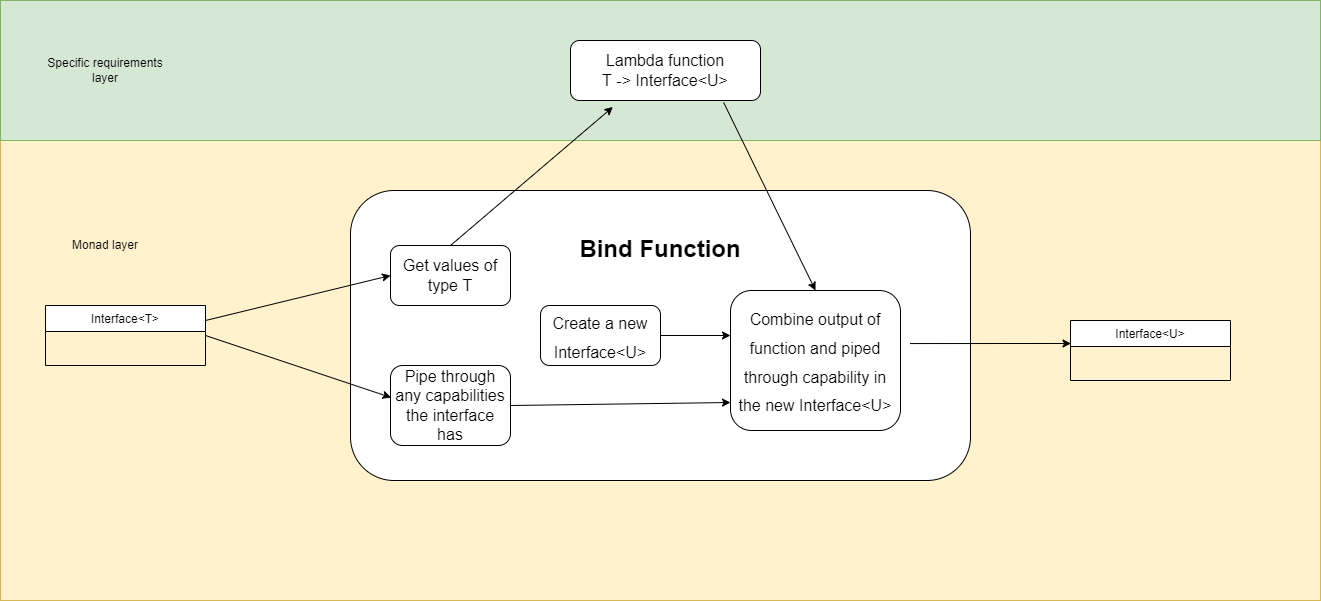
As you can see, monads are a 2-layer pattern. The two layers correspond roughly with ALA’s application and programming paradigms layers. The code that uses Bind to compose functions, and the lambda functions themselves are in the application layer. The Bind function and the Interface<T> are in the programming paradigms layer. Often monads come with a set of more specialized functions such as Sort, Filter and Sum. These would go in the equivalent of the domain abstractions layer. These functions either use Bind, or do the equivalent logic as Bind themselves.
The functions that are being composed take a T and return an Interface<U>. It is tempting to think that the Bind function simply returns the Interface<U> that is returned by the function, because they have the same type. But that is not usually the case. Bind usually creates a new object that implements Interface<U>, and then combines information from both the input Interface<T> and the output of the function to provide the output Interface<U>. That’s what the diagram is trying to convey.
In many explanations of monads, they call the interface the monad type, or a wrapped type, or a container type, or a type in a box, or an amplified type, or just the notation M T. I don’t think any of these terms are helpful in understaning monads. The wrapped, container and box terms don’t work well for deferred monads, which don’t actually contain a value. They contain a means of getting a value. For example, the deferred version of a list is IEnumerable. If our function returns an IEnumerable, that’s not really a container or box.
The term amplified just introduces another seemingly abstract concept which is unnecessary. And the term Monad type or the notation M T seems a bit circular - let’s not explain monads in terms of monads. So I prefer to think of the thing that the Bind function takes and returns as simply a chaining interface. It sometimes has one implementation, such as Task or List, but often it has more than one implementation such as IMaybe or IEnumerable. Usually the Maybe monad uses IMaybe with two implementations, one for when there is a value and one for when there is no value.
So generally I just think of it as Interface<T>.
The monad pattern requires three things: * an Interface<T> (the chaining interface) * a constructor or method for making ordinary values of type T into an object that implements Interface<T> * a Bind function that takes an Interface<T>, returns an Interface<U>, and is passed a function of the form Func<T, Interface<U>>.
The constructor or method for getting ordinary values into Interface<T> form is required to get started at the beginning of a chain.
For push style monads, we didn’t exactly follow this definition because the functions didn’t always return the chaining interface, but they did something equivalent.
The chaining interface and the Bind function can pipe through any extra information or capability we want through the interface. We could, for the sake of a silly example, pipe through an audio stream if we really wanted to. We could compose functions to modify the stream.
SelectMany vs Select
The LINQ opertors such as Select and SelectMany use IEnumerable as their chaining interface - they take an IEnumerable and return an IEnumerable. This allows them to be composed in chains using dot operators.
Select is like Map. It takes a function that maps inputs to outputs in one to one correspondence. Aggregating operators such as Sum produce a single output from many inputs. SelectMany is the opposite - it produces many outputs from a single input.
Select is probably the most common operator used in LINQ statements. So why is SelectMany the fundamental Bind operator of the IEnumerable monad and not Select?
It’s because SelectMany is the one that strictly fits the monad pattern as described in the previous section. For a monad, the function being composed generally returns the same interface as the chaining interface. SelectMany is the one that does that. Select takes a function that returns a value, not an interface.
So while we sometimes think of the whole LINQ library as being monadic, strictly speaking only SelectMany is part of the monad.
Summary of monad benefits.
-
Monads allow us to simply compose functions declaratively in the top layer to implement a user story. How everything executes is handled by the Bind function in a more abstract lower layer.
-
The declarative code in the top layer is a different programming paradigm from imperative. It’s called dataflow, because we are directly composing a flow of data from functon to function, irrespective of how the underlying execution will work.
-
Monads make it possible for the application code to concentrate on expressing user stories, and not be concerned with execution details.
-
Monads take care of passing data from function to function, without the application layer code needing to handle it.
-
We can compose as many functions as we like in chains of arbitrary length without any nesting of brackets or indenting.
-
The execution code in the Bind function can handle many different cases of logic that would otherwise have been messy imperative code between function calls.
-
Monads make it possible for application code itself to be pure functional code, even though the structure of connected objects that is built is not.
-
The application code examples that use the deferred versions of Bind look much the same as the immediate versions. That’s because at the application level, we are still just declaratively composing functions.
-
We prefer to implement deferred versions of Bind because then we have the option of executing them straight away as if it was immediate, or use them as part of a larger program for later execution.
-
Deferred monads make it possible to separate all code that expresses user stories from code that implements computing details.
6.2. ALA compared to monads
Now that we have an understanding of monads, and deferred/push monads in particular, we are in a position to compare them with ALA.
-
In the application layer, monads compose functions whereas ALA composes objects with ports.
-
Composing functions is a dataflow programming paradigm, whereas composing objects with ports is a multi programming paradigm.
-
Composing functions creates mostly a chain structure whereas composing objects with ports creates an arbitrary network structure. Monads can form networks as when two streams are merged, but in practice most functions have a single input and single output.
-
Both deferred monads and ALA build a structure of objects which is subsequently executed in a second phase. This separates declarative application code from execution model code.
-
Both monads and ALA use pure functional code for the application code in the top layer. In this respect ALA and monads achieve the same job by putting the dirty computational work inside a pre-written Bind function in the case of monads or classes in the case of ALA. This dirty work can include private state and I/O side-effects.
-
ALA’s domain abstraction objects are more versatile than functions because they can more naturally have many ports, and the ports can use different programming paradigms. This allows for abstractions suitable for composing all aspects of user stories, such as UI, schema, business rules, etc.
For example, you can have a single domain abstraction with a UI port (to be attached somewhere in the UI) multiple event driven ports (for mouse clicks) and a dataflow port (for binding to a data source).
-
Dataflow ports can each use either push or pull as appropriate in each particular case, whereas monads tend to encourage you to use only one type or the other as a programming style, e.g. LINQ or reactive extensions.
-
'Push' dataflow interfaces can be used for either synchronous or asynchronous dataflows. So in ALA we default to using push style dataflows unless 'pull' has a particular advantage in a particular case. This allows instances of abstractions to be wired either synchronously or asynchronously. In other words the choice of synchronous or asynchronous is deferred until the application user stories are written. Asynchronous can be chosen, for example, when two instances of abstractions will communicate over a network, or on differnt threads, and synchronous can be chosen when the user story knows that the two will always communicate on the same thread.
'Push' style dataflows (reactive extensions) appear to be less popular in the industry. I don’t understand why. Perhaps it’s because the IObservable interface isn’t a true push style since the destination usually starts the flow of data by Subscribing (cold observables)? This mix of pull and push behaviour in the IObservable/IObserver pair is confusing and not easily amenable to network or miltithreaded systems that would otherwise suit push programming paradigms. Hot observables do not need the pull to initiate the data flow, but they have to avoid using both OnCompleted and OnError, otherwise the whole chain must be resubscribed. So they don’t use the full benefits of the IObserver interface.
-
ALA programming paradigms, which are usually interfaces, are analogous to monad chaining interfaces. ALA programming paradigm interfaces can use any of the chaining interfaces such as IMaybe, IEnumerable, or Task or futures.
-
A monad’s Bind function is partially analogous to ALA’s WireTo function, because it implements the wiring. However the Bind function is different for every different monad type because it includes the deferred, run-time, common, execution code of the monad. ALA’s WireTo function only does the wiring. It does not normally include any common run-time code, although it can sometimes be overridden to do special wiring. Instead, in ALA, that common code goes into the programming paradigm, which may use intermediary objects. WireTo is generally the same WireTo for all programming paradigms and therefore all wiring up of an entire application is done using it.
-
Monads usually use deferred execution and ALA always uses deferred execution, so in this respect they are similar. Both build an object structure which you then run after the wiring up is completed. They both have two phases, the wiring up phase and the run-time execution phase. However, in ALA, we always separate out all the wiring code for the entire application and then set the whole application running. Deferred monads are often wired up as short chains and then executed in the same code statement or nearby.
By building the entire application first, ALA completely separates code into a top layer at the abstraction level of specific user stories, and a second layer that consists of domain abstractions that contain all the code that executes at run-time. In this way the top layer has all the declarative code that expresses the application and the second layer has all the imperative code that knows how to do general computation work at runtime.
-
ALA’s application layer corresponds loosely with functional code that composes functions. ALA’s programming paradigms correspond loosely with Bind functions. And ALA domain abstractions correspond loosely with the set of methods that generally come with a monad library such as Select or Where.
6.2.1. Composing with plain objects instead of functions.
By using plain objects the barrier to understanding seems lower than for monads, at least for developers already familiar with objects. Functional programming, and monads in particular, seem to have quite a high barrier to entry unless you are a mathematician. The world needs the programmers who are able to understand objects but do not necessarily understand mathematical notation. I’m not sure what would happen if all universities only taught functional programming so that everyone is introduced to pure functions first. Perhaps then it would be objects which have a barrier to entry.
ALA’s domain abstraction objects are easier to understand than monads because they are plain objects. The mental model of composition in ALA is wiring instances of domain abstractions by their ports, which is conceptually just a component model. Monads compose functions so the mental model is primarily oriented to composing a chain of functions as a dataflow. To make an analogy with electronics, ALA is like composing ICs (integrated circuits with many pins with many functions) and monads is more like composing two-port components such as resistors, capacitors, inductors and transistors.
There seems to exist computing problems that are best described using state. Objects are the language feature that provides for this. Monads end up using objects with state anyway - they are just hidden beneath the covers.
The only slightly difference between ALA’s domain abstraction objects and plain object oriented objects is the use of ports. Port are used for all run-time input and outputs. Any programmer with familiarity with dependency injection can understand that a port is just an implementiion of dependency injection. A port is implemented simply as a field of the type of an interface, or is an implemented interface. As with normal dependency injection, the field is assigned a reference to another object that implements the port interface.
Unlike conventional dependency injection, the field is not assigned by the constructor or any setters. Instead the field is always assigned through use of WireTo or WireIn.
The difference between ALA and conventional dependency injection is that the interface used must be more abstract than either of the classes. It cannot be thought of as an abstract base class. It is even more polymorphic than that. This type of interface is called a programming paradigm, and can be implemented by many disparate classes. Therefore, the dependency injection cannot be container based. Instead the application code must explicitly instantiate the required objects and then wire them together.
Because ALA uses plain objects, and plain interfaces as their ports, ALA developers can add new domain abstractions and programming paradigms themselves. In the functional world, developers can certainly write new monad types, but it doesn’t seem that easy, and seems generally left to library developers. The abstraction level of these libraries is therefore generally not as close to the domain, and does not make a DSL. In ALA, the set of domain abstractions and programming paradigms that you write is a DSL.
6.2.2. ALA vs monad syntax
Although ALA supports multiple programming paradigms, the dataflow programming paradigm is quite a common one. So we will have many domain abstractions like those that come with monad libraries like Select, Where and Sum. It is worth comparing the syntax of ALA using dataflows with monad syntax.
Here we are comparing the code in the top layer, the code that describes a user story. Both monads and ALA use fluent style with dot operators.Here is the syntax for monads:
source.Filter(x=>x>=0).Select(x=>sqrt(x))And here is the syntax for ALA:
source.WireIn(new Filter<int,bool>(x=>x>=0)).WireIn(new Select<int,int>(x=>sqrt(x))In the monad version, the Filter and Select functions do both the wiring and specify the operation to be wired, whereas in the ALA version these are kept separate. Keeping them separate has advantages that we will discuss shortly.
The ALA code can be generated from a diagram. However, there is nothing stopping us achieving exactly the same syntax as the monad version if we really want to. We just create extension methods that both create an instance of, and wire up, each abstraction such as Select and Filter:
namespace DomainAbstractions
{
    static class ExtensionMethods
    {
        public static IChainable Select<T, U>(this IChainable source, Func<T,U> function)
        {
            var select = new Select<T, U>(function);
            source.WireIn(select);
            return select;
        }
    }
}
namespace DomainAbstractions
{
{
public static IChainable Filter<T>(this IChainable source, Func<T,T> function)
{
var filter = new Filter<T>(function);
source.WireIn(filter);
return filter;
}
}
}The code for these extension methods would be located in the same abstractions as the Select and Filter classes respectively.
Note that IDataFlow is the type of the ports being wired. IDataflow is a push interface (similar to IObserver). So IDataFlow goes in the forward direction (the same direction as the data flows). The Select and Filter extension methods can’t be defined on IDataFlow. We need an interface on which to define Select and Filter. This interface must go in the reverse direction, from destination to source. So that’s what IChainable is for. IDataFlow and IChainable are analogous to the IObserver and IObservable interfaces respectively. Note, though, that IChainable only exists to give us an interface on which to define the extension methods. It doesn’t do anything else, so it contains no methods:
interface IChainable {}It doesn’t have a Subscribe method because the Select and Filter extension methods did the wiring up of the IDataFlow ports of the instances of the abstractions.
Note: normally IChainable would have a type parameter: IChainable<T>. That would allow type inference to be used for the type parameter of methods that are defined on it such as Select<T,U> and Filter<T>, etc. However, the compiler can't always successfully use type inference for that second type parameter, U. It can if the second parameter passed to Select is a function that returns a certain type. But it can't if the second parameter is an action, which is the case for the ObserverPushAction domain abstraction. Therefore I have removed the type parameters from IChainable so that its less confusing, and Select etc will always need to have its types passed in explicitly.
In ALA we keep the WireIn and new operators separate for the following reasons:
-
In ALA, Domain abstractions are generally at a slightly more specific level of abstraction than monad library functions (specific to the domain to support the construction of user stories). So, domain abstractions are written by the application developer much more frequently than new monads are written. They are extremely simple to write once the concept of ports is understood, because the ports make them zero coupled with one another and with the application layer above. The only difference from plain classes is that you have to know that input ports must use implemented interfaces from the programming paradigms layer, and output ports must be plain private fields of the types of these same interfaces. We don’t want the extra burden of adding a corresponding extension method.
-
In ALA we can choose between WireIn and WireTo depending on whether we want to chain instances of abstractions or do fanout wiring. Monad library functions alway return the next object in the chain, so only naturally wire up chains.
-
The mental model of components with ports that you explicitly wire up is more versatile than the mental model of composing functions as a dataflow chain. Functions can be thought of as have multiple ports, for example the merge function can have two input streams, but the fluent syntax of combining monadic functions does not suit it.
-
Composing monad functions is only a dataflow programming paradigm. In ALA many diverse programming paradigms can be used. The diverse programming paradigms represent different meanings of composition. For example, we can compose the UI. The code below puts a Button, TextBox and Grid inside a window.
ALA wiring codewindow.WireTo(new Button().WireIn(...)) .WireTo(new TextBox().WireIn(...)) .WireTo(new Grid().WireIn(new DynamicDataSource().WireTo(...)));The button can be further wired using an event driven programming paradigm. The Textbox can be further wired to its data using dataflow. The Grid can be wired using a dynamic dataflow programming paradigm to a dynamic data source, which could itself be wired using a schema programming paradigm.
-
Deferred monads look like operations on data, but obscure the fact that they build a structure of objects for later execution. This is confusing until you get used to it. The WireTo and WireIn operators together with the new operator make it explicit that you are building a structure of objects as a program that you can then set running.
-
Because domain abstractions can have multiple ports, WireIn and WireTo allows us to specify which port we want to wire when it could be ambiguous.
-
Inherent in the requirements of a typical application is really a network of relationships. This network is often best represented by a diagram. Explicit WireIn and WireTo operators allow us to directly translate a diagram to code. Also, diagramming tool can automatically generate the wiring code containing using WireTo and new.
6.3. Using monads in an ALA application
Although composing with objects is generally more versatile than composing with functions, if you already have a monad library containing functions such as SelectMany, Select, Where, Sort, Aggregate, etc, we would certainly want to make use of it in ALA applications. There would be no sense in reinventing that functionality as 2-port classes. You can use the monad library for some dataflow parts of the program.
In this section we discuss two methods to use monads within an ALA application:
-
The first method is to use IObservable as the interface for some of the ports of your domain abstractions. Then two instances of these domain abstractions can be wired with a reactive extension expression inbetween. Although n IEnumerabe version is possible, we will only show an example using the IObservable interface because that is more compatible with how ALA programming paradigms gnerally work (push by default). We will give examples for both static and dynamic type dataflows.
-
The second method is to write a general purpose domain abstraction that can be configured with a monad expression. The domain abstraction has input and output ports using ALA’s DataFlow interface. We will do both an IEnumerable and an IObservable version of this domain abstraction.
6.3.1. Domain abstractions with IObservable ports
Statically typed
The first way to use monads with ALA is to use the chaining interface, such as IObservable, for the ports on some domain abstractions. For example, we could have a domain abstraction for a CSV file reader that has an output port of type IObservable<DataType>. Then we can have a domain abstraction called ObservableToSerial that has an input port of type IObservable.
We can then wire there two end instances via some .Where or .Select functions inbetween using monad functions that already exist in the reactive extension library. Here is some example application code:
class Program
{

    static void Main()
    {
        var outputer = (6)
        ((IObservable<DataType>)new CSVFileReaderWriter<DataType>() { FilePath = "DataFile1.txt" }) (1)
        .Select(x => new { Firstname = x.Name.SubWord(0), Number = x.Number+1 } ) (3)
        .Where(x => x.Number>48) (4)
        .WireInR<T>(new ObservableToSerial<T>(Console.Writeline)); (5)

        var program = new StartEvent().WireTo(outputer); (7)
        program.Run(); (8)
    }

    private class DataType (2)
    {
        public string Name { get; set; }
        public int Number { get; set; }
    }
}| 1 | We start the chain by instantiating a CSVFileReaderWriter and providing it with a filepath. |
| 2 | We also give CSVFileReadWriter a type, DataType, which corresponds with the fields in the CSV file we are going to read. (This is not a dynamic CSV file, so we are going to do this program completely with compile-time type checking using type inference.) |
The CSVFileReaderWriter domain abstraction can have multiple output ports of different types, but the one we are going to wire is an IObservable<DataType>. CSVFileReaderWriter implements this interface. To specify which port we are wiring we simply cast the CSVFileReaderWriter to IObservable<DataType>. It’s a shame we had to have DataType appear twice in the program.
| 1 | We wire the CSVFileReaderWriter’s IObservable port to a Select function. Like a monad, Select returns another IObservable, with a different type. The compiler can use type inference to generate this type. |
| 2 | We wire the output of Select to a Where function. Where returns yet another IObservable with a type using type inference. |
| 3 | We wire the output of Where to a new domain abstraction called ObservableToSerial. (The type inference doesn’t work here, but we will fix that soon.) |
| 4 | We store the ObservableToSerial in a local variable called outputer because we need to wire to it in another place. |
| 5 | outputer has an IEvent input port which is used to start the transfer. With IObervables, the data transfer is started from the destination end. We wire a StartEvent domain abstraction to the outputer. StartEvent has an IEvent output port and can be used to set a program running. We store the StartEvent in a variable called program. |
<9) To start the program running we call program.Run(), which is a method in the StartEvent.
The line labelled 5 in the listing doesn’t compile. It’s what we would like to have written to get the type inferencing working starting from the CSVFileReaderWriter right through to the outputer. The reason it doesn’t compile is that new ObservableToSerial<T> needs a type to be specified for T. The WireInR<T> knows the type from its this parameter. But you can’t get the compiler to transfer that type to the second parameter of WireInR, the new ObservableToSerial<T>.
The solution is to use an extension method to do the WireInR and the new ObservableToSerial<T>. Here is a suitable extension method:
public static ObservableToSerial<T> ToConsole<T>(this IObservable<T> observable) where T : class
{
    var o = new ObservableToSerial<T>(Console.WriteLine);
    observable.WireInR(o);
    return o;
}
Using this extension method, here is the application again:
    static void Application()
    {
        var outputer =
        ((IObservable<DataType>)new CSVFileReaderWriter<DataType>() { FilePath = "DataFile1.txt" })
        .Select(x => new { Firstname = x.Name.SubWord(0), Number = x.Number + 1 })
        .Where(x => x.Number > 48)
        .ToConsole();

        var program = new StartEvent().WireTo(outputer);
        program.Run();
    }
}
Type inference now works all the way through the dataflow chain. We only had to specify the type of the data in the CSV file.
Dynamically typed
This next example does the same functionaility as the previous example, that is demonstrating mixed use of domain abstractions with IObservable ports and reactive extension monads. However, this time it does not statically define the data type at compile-time. In other words, it makes no assumptions about the data schema in the CSV file. Instead, it determines everything at run-time. If any code tries to access specific data that doesn’t exist or has the wrong type, run-time exceptions are thrown rather than compiler errors.
Since the CSV file is now considered dynamic, it has two header lines, one to name the columns and one that defines the types of the columns. Knowledge about these header lines is contained in the CSVFileReaderWriter abstraction. The first half of the code writes some data to the CSV file to ensure header lines are created.
static void Application()
{
    var csvrw = new CSVFileReaderWriter() { FilePath = "DataFile2.txt" }; (1)

    // First write some data to the file

    IObserverPush<ExpandoObject> writer = csvrw; // writer port (2)
    writer.OnStart(); (3)

    dynamic eo = new ExpandoObject(); (4)
    eo.Number = 47; (5)
    eo.Name = "Jack Up";
    writer.OnNext(eo); (6)

    eo.Number = 48; (7)
    eo.Name = "Wynn Takeall";
    writer.OnNext(eo);

    eo.Number = 49;
    eo.Name = "Rich Busted";
    writer.OnNext(eo);

    writer.OnCompleted(); (8)

    // Now wire the output port of the CSVFileReaderWriter via a Select and a Where to an outputter.

    var outputer = new ObservableToSerial<ExpandoObject>(Console.WriteLine); (9)(10)

    ((IObservable<dynamic>)csvrw)  (11)
        .Select(x => new { Firstname = ((string)x.Name).SubWord(0), Number = x.Number + 1 })
        .Where(x => x.Number > 48)
        .WireInR(outputer);

    var program = new StartEvent().WireTo(outputer); (12)
    program.Run(); (13)
}| 1 | First we instantiate a CSVFileReaderWriter domain abstraction. Notice how this abstraction is not generic like we had before. Instead its ports use the ExpandoObject class. |
| 2 | Get a reference to the input port of the CSVFileReaderWriter. This input port has type IObserverPush<ExpandoObject>. The IObserverPush programming paradigm is like IDataFlow, but can handle batches of data:
As you can see it is a standalone version of IObserver. It doesn’t need a corrsposnding IObservable interface. It operates by itself. It is explained in detail later. |
| 3 | Calling OnStart on the input port causes CSVFileReaderWriter to create a new file. |
| 4 | Create a temporary ExpandoObject. This is a usefull class when using dynamic typing which can have properties added at run-time. |
| 5 | Add fields to the ExpandoObject. |
| 6 | Give the ExpandoObject to the input port of the CSVFileReaderWriter, which will write the data to the CSV file. |
| 7 | Write more records in the same way. |
| 8 | Complete writing the CSV file. |
| 9 | Instantiate an ObservableToSerial for the end of the chain. ObservableToSerial has an IEvent input port called trigger that is used each time we want the program to go (by subscribing to its data source). |
| 10 | Configure the ObservableToSerial to output to the console. |
| 11 | Wire the chain up starting from the CSVFileReaderWriter through to the ObservableToSerial via two LINQ operators. IObservable ports are used the whole way. The IObservable output port of the CSVFileReaderWriter is selected by the cast.
One unusual thing you may notice about this ALA program is the use of WireInR instead of WireIn that we would normally use to wire things in a chain. A.WireInR(new B()) actually wires in the reverse direction from normal, that is from B to A. You use it like you would use WireIn, in the same direction as the dataflow, but it actually wires in the opposite direction. This is because IObservable, the programming paradigm interface being used, must be wired in the opposite direction as the dataflow, like a pull interface. The A object implements IObservable and the B object has a field of type IObservable. So the wiring must go in the reverse direction of the data flow. WireInR is implemented simply as WireInR(this object A, object B) {WireIn(B, A);} |
| 12 | Wire an instance of a StartEvent to the ObservableToSerial Trigger input port. |
| 13 | Make the program run by telling the StartEvent to output an event. |
6.3.2. Domain abstraction configured with monads
This is the second method of using monads in an ALA application.
It uses a domain abstraction that can be configured with a monad expression. This domain abstraction uses your normal ALA dataflow programming paradigm forits its input and output ports. We will do two versions, one configured with an IEnumerable chain and one configured with an IObservable chain.
Configuring with IEnumerable monads
Let’s call the domain abstraction EnumerableQuery. You configure an instance of EnumerableQuery with a LINQ expression.
Here is an example program using EnumerableQuery. EnumerableQuery uses IDataFlow as the programming paradigm for its ports. We chain up three of them and configure them all with a similar query:
static void Application()
{
var proxySource1 = new EnumerableProxySource<int>(); (1)
var query1 = proxySource1.SelectMany(x => new[] { x * 10 + 1, x * 10 + 2, x * 10 + 3 }).Select(x => x + 1); (2)
var proxySource2 = new EnumerableProxySource<int>(); (1)
var query2 = proxySource2.SelectMany(x => new[] { x * 10 + 1, x * 10 + 2, x * 10 + 3 }).Select(x => x + 2); (2)
var proxySource3 = new EnumerableProxySource<int>(); (1)
var query3 = proxySource3.SelectMany(x => new[] { x * 10 + 1, x * 10 + 2, x * 10 + 3 }).Select(x => x + 3); (2)
var userStory = new StartEvent(); (3)
userStory
.WireIn(new ValueToDataFlow<int>(0)) (4)
.WireIn(new EnumerableQuery<int, int>(proxySource1, query1) { instanceName = "Query1" }) (5)
.WireIn(new EnumerableQuery<int, int>(proxySource2, query2) { instanceName = "Query2" }) (6)
.WireIn(new EnumerableQuery<int, int>(proxySource3, query3) { instanceName = "Query3" })
.WireIn(new DataFlowToSerial<int>(Console.Write)); (7)
userStory.Run(); (8)
}| 1 | To build a LINQ expression, you need to start with a source that implements IEnumerable. Since we don’t have an actual source, we will use a proxy for the source. That’s what the EnumerableProxySource is. |
| 2 | An example LINQ expression consisting of a SelectMany and a Select. |
| 3 | Instantiate a StartEvent domain abstraction, which we will use to tell the user story to run. |
| 4 | Instantaite a domain abstraction that represents a simple scalar value and will output that value to its output IDataFlow port when told to by its IEvent input port. |
| 5 | Wire in the first of the three EnumerableQuery domain abstractions. EnumerbaleQuery has an input IDataFlow port and an output IDataFlow port. Configure it with the LINQ expression. To do that we give it both the proxySource object and the LINQ expression object. EnumerableQuery will receive data pushed to its input port, apply the LINQ expression to it, and push the result out its output port. |
| 6 | We chain up three of the EnumberableQuerys to demonstrate normal ALA wiring up of this abstraction. |
| 7 | We wire the final output to the console using an instance of a DataFlowToSerial domain abstraction configured to give its serial stream to the Console. |
| 8 | Tell the user story to run. |
Here is the output of the program:
The initial value of zero expands to 27 numbers because of the SelectMany in each of the LINQ expressions.
Internally, what EnumerableQuery does is every time an input data arrives, it executes a foreach on the query. When the query asks for for data from the proxySource, the proxySource returns the data that came into the input port.
Here is the EnumerableQuery domain abstraction:
class EnumerableQuery<T, U> : IDataFlow<T> // input port (1)
{
private readonly EnumerableProxySource<T> proxySource;
private readonly IEnumerable<U> query;
public EnumerableQuery(EnumerableProxySource<T> proxySource, IEnumerable<U> query) { this.proxySource = proxySource; this.query = query; proxySource.Enumerable = getIEnumerableForInputData(); } (3)
private IDataFlow<U> output; // output port (2)
private T inputData;
private IEnumerable<T> getIEnumerableForInputData() (4)
{
yield return inputData;
}
void IDataFlow<T>.Push(T data) (5)
{
this.inputData = data;
foreach (var x in query) output?.Push(x);
}
}| 1 | The input port is an IDataFlow<T> |
| 2 | The output port is an IDataFlow<T> |
| 3 | The constructor takes a LINQ expression (both its proxySource object and the query itself) and saves them to local variables. The constructor also sets up proxySource to get its data from an IEnumerable. |
| 4 | The IEnumerable is returned by getIEnumerableForInputData. This IEnumerable simply returns the data that has come in on the input port. The IEnumerable is implemented with a method that contains a yield return. |
| 5 | The implementation of the input port is what drives the domain abstraction. It first saves the incoming data so that the query can use it as its source, then enumerates the LINQ query. The results are given to the output port. |
The code above can be found in a working example program on Github in the IEnumerableMonad repository here: https://github.com/johnspray74
Configuring with IObservable monads
In the previous example, we created a domain abstraction that can be configured with a LINQ query. In this next example, we create a domain abstraction that can be configured using reactive extensions.
When all else is equal, I prefer reactive extensions over LINQ because it can do asynchronous and synchronous.
We could have done this example using IDataFlow ports just as we did in the previous example. However, the IObserverPush programming paradigm that we briefly introduced earlier is more appropriate. IDataflow handles an open-ended stream of data, whereas IObserverPush can handle open-ended batches of data.
Here is a user story example of using this domain abstraction.
static void Application()
{
var subject1 = new Subject<int>(); (1)
var query1 = subject1.SelectMany(MutiplyBy10AndAdd1Then2Then3).Select(x => x + 1); (2)
var subject2 = new Subject<int>();
var query2 = subject2.SelectMany(MutiplyBy10AndAdd1Then2Then3).Select(x => x + 2);
var subject3 = new Subject<int>();
var query3 = subject3.SelectMany(MutiplyBy10AndAdd1Then2Then3).Select(x => x + 3);
var userStory = new StartEvent(); (3)
userStory
.WireIn(new ValueToObserverPush<int>(0)) (4)
.WireIn(new ObservableQuery<int, int>(subject1, query1)) (5)
.WireIn(new ObservableQuery<int, int>(subject2, query2))
.WireIn(new ObservableQuery<int, int>(subject3, query3))
.WireIn(new ObserverPushToSerial<int>(Console.Write)); (6)
userStory.Run(); (7)
}
static IObservable<int> MutiplyBy10AndAdd1Then2Then3(int x) (8)
{
return Observable.Create<int>(observer =>
{
observer.OnNext(x * 10 + 1);
observer.OnNext(x * 10 + 2);
observer.OnNext(x * 10 + 3);
observer.OnCompleted();
return Disposable.Empty;
});
}| 1 | First we need a proxy source object that implements IObservable on which to build our reactive extensions expression. The RX library provides a suitable class that we can use for this called Subject. |
| 2 | Create the RX expression consisting of a SelectMany and a Select. |
| 3 | The user story will consist of three ObServableQuerys wired up in a chain. Data transfers are intitaited at the source. So we instantiate a StartEvent domain abstraction to give us a way of starting (or restarting) the dataflow. |
| 4 | The StartEvent instance is wired to the start port of an instance of ValueToObserverPush using an IEvent programming paradigm. ValueToObserverPush is a simple domain abstraction that is configured with a single value. It has an IObserverPush output, and will output its value when it gets a signal on its start port. |
| 5 | The ValueToObserverPush is wired to an ObservableQuery using the IObserverPush programming paradigm. ObservableQuery is configured with an RX expression. Both the subject and the expression itself must be passed in. |
| 6 | After the three ObservableQuerys are wired, the output is wired to an instance of ObServerPushToSerial, where it is converted to text to be displayed on the Console. |
| 7 | Now that the user story is all wired up, we can run it. It can be run more than once. |
| 8 | The function passed to the SelectMany is implemented using the Observable.Create method, which is a convenient way to do it for our purposes here. |
Here is the code for ObServableQuery:
class ObservableQuery<T, U> : IObserverPush<T> // input port (1)
{
private readonly Subject<T> queryFrontEnd;
private readonly IObservable<U> query;
public ObservableQuery(Subject<T> queryFrontEnd, IObservable<U> query) { this.queryFrontEnd = queryFrontEnd; this.query = query; } (3)
private IObserverPush<U> output; // output port (2)
private IDisposable subscription = null;
void IObserverPush<T>.OnStart() (4)
{
output.OnStart(); (5)
subscription?.Dispose(); (7)
subscription = query.Subscribe( (6)
(data) => output.OnNext(data),
(ex) => { output.OnError(ex); terminated = true; }
() => output.OnCompleted());
}
void IObserver<T>.OnNext(T data) (8)
{
queryFrontEnd.OnNext(data);
}
void IObserver<T>.OnError(Exception ex) (9)
{
queryFronEnd output.OnError(ex);
}
void IObserver<T>.OnCompleted() (10)
{
queryFronEnd.OnCompleted();
}
}| 1 | The input port is an IObserverPush |
| 2 | The output port is an IObserverPush |
| 3 | The constructor configures the domain abstraction with an IObservable expression. Both the front end Subject object and the RX expression object itself are passed in. These are saved as local variables. |
| 4 | An OnStart call prepares for a new batch of data. |
| 5 | The OnStart signal is propagated to the output port so it goes right through the chain to prepare the entire chain for the data sequence. |
| 6 | The query that we were configured with is subscribed to. This does not cause data to flow from the RX expression yet. Outputs from the RX expression are routed directly to the domain abstraction’s output port. The subscribe must be done here rather than in the constructor because if OnStart is called again for a subsequent batch of data, Subscribing needs to be done again to 'reset' the RX expression if it had completed. |
| 7 | If the query had previously been subscribed to, it probably had an OnCompleted or OnError which would prevent it working until it is subscribed to again. But we don’t want to subscribe to it twice, so we first unsubscribe. |
| 8 | When data arrives at the input port, it is given to the query via the Subject object. |
| 9 | Any exception coming in from the input is passed through to the output via the query. If the query has already generated an exception it will likely discard it. |
| 10 | The OnCompleted from the input is also passed through to the output via the query. |
That completes our examples of how you can use monads within an ALA application.
This has been a long section contrasting monads and ALA. In summary ALA solves the same problem that monads solve, that of composing more abstract computational units to create more specific computational units. But where monads are about composing functions, ALA composes objects. While pure functions are mathematically simpler than objects, many computations are more naturally expressed using state. That’s why ALA is object oriented. In other words, sometimes objects just make better abstractions than functions.
But if you already have an existing monad library, it makes sense to use it within an ALA application.
6.3.3. IObserverPush interface
We used the programming paradigm interface IObserverPush a couple of times in the examples previously.
Here it is again:
interface IObserverPush<T> : IObserver<T>
{
    void OnStart();
}Nothice that it is the IObserver interface with one added method: OnStart.
Now we can explain the reasoning behind this programming paradigm, and compare it with the IObserver/IObservable pair.
IObserverPush<T> is similar to IDataFlow<T>, but with the ability to handle batched data and to propagate errors down the data flow.
This interface is the 'pure push' version of the IObservable/IObserver pair. Remember that while IObserver is a push style interface, IObservable is not. The Subscribe method of IObservable is more of a pull style that usually gets the flow of data started. So its hard to use IObservable asynchronously or over a network.
Data transfers using IObserver are usually triggered from the destination end. It does so via IObservable. For example, ObservableToSerial in the previous section must subscribe to 'pull' the data. So Subscribe does two things: 1) it wires the IObserver interface in the opposite direction, and 2) it (usually) starts the data transfer. The source will then push the data back using the IObserver interface.
Sometimes Subscribe only wires the IObserver, and thereafter the source initiates the data transfer whenever it likes. This is called a hot observable. OnCompleted and OnError cannot really be used with hot observables because they usually stop everything. If the source does use OnCompleted or OnError, then the source must really send the data in response to the Subscribe. If OnCompleted or OnError are called, the detsination must unsubscribe and resubscribe to get the next batch of data. The Subscribe method, therefore, is not just used for wiring - it is usually used to start the transfer.
I find this behaviour of IObservable/IObserver doesn’t suit permanently wired user stories like we do in ALA. Besides, IObservable and IObserver seems to be a weird mix of 'push' and 'pull' styles. What I want is a purely push programming paradigm, that can be permanently wired, can batch the data, and can propagate errors down the dataflow chain.
The other problem with the IObservable interface is that the destination wires itself to the source. The destination of a communication should never wire itself to the source if its in the same layer. It’s fine if the source is in a lower (more abstract) layer. But general wiring up within an abstraction layer should always be done by a higher layer.
So to fix all these problems with the IObservable/IObserver pair, I use IObserverPush as an ALA programming paradigm.
The OnStart method effectively takes the place of the Subscribe method in that it will allow data to flow again after an OnCompleted or OnError. In other words, we can permanently wire IObseverPush, and it will work for ongoing batches of data even after OnCompleted or OnError occurs in each batch. The wiring aspect of the Subscribe method is not needed. In ALA the layer above will wire up the IObserverPush interface. The IObservable interface is therefore completely redundant.
In summary, IObserverPush
-
is used instead of IObserver/IObservable
-
is a pure push programming paradigm
-
like IObserver, goes in the direction of the dataflow
-
requires the layer aobve to wire it up
-
is designed to be permanently wired, but can still handle batches of data using OnCompleted, or OnErrors.
6.4. Encapsulation, polymorphism and inheritance
ALA replaces encapsulation with abstraction.
ALA removes associations and inheritance and instead uses composition (provided the composition uses a more abstract abstraction).
ALA replaces polymorphism with zero coupling.
The first two we know as fundamental principles in ALA, and have already been discussed in chapter three.
The third statement requires some elaboration.
In the meme pool of software engineering we have at least five memes for the one concept. These are polymorphism, information hiding, protected variations, dependency inversion principle and open closed principle.
I shall argue in their individual discussion later that none of them is a principle. All five are just a simple pattern. The motivation is that if you have code that couples knowledge of different 'things', you extract the knowledge into their own modules. Now when the 'thing' changes, you can change it or swap it out without affecting the client module. Switch statements were a smell in traditional code that different things were mixed.
You may already have separated out one implementation of a thing. So now your client code talks to a concrete thing. The conical example is a particular database. But now you need to use a different thing. Instead of putting in a switch statement everywhere to talk to different databases, you use the polymorphism / information hiding / protected variations / dependency inversion / open closed pattern.
The pattern itself consists of an interface. That’s it. All those memes all trying to tell you to use an interface. Oh, and another one - if you have heard the phrase "program to interfaces".
On top of that, single responsibility also pretty much forces the use of an interface. Referring to a peer concrete object is always a second resposibility.
ALA does not use this pattern.
To understand why, lets call the client module B and the modules that implement the interface, C1, C2 etc. B doesn’t know which of the C modules it is talking to at run-time. If we want it to be C2 for a particular application, we have higher level code that injects C2 into B.
It’s important that we realize that in this pattern the interface is owned by B. It describes what B requires. It is cohesive with B. It is part of abstraction B. This still the case even if the interface is split out into a module or even a different compilation unit of its own.
Therefore C1, C2 etc have a dependency on B. They implement B’s requirements. They collaborate with it. The dependency in the design is just inverted from what it might have been. C1 & C2 are coupled with B.
So this is illegal in ALA (assuming B and C1, C2 etc are all at a similar level of abstraction, which they likely are. That’s why for ALA I have stated that the equivalent is zero coupling. ALA replaces the dependency with nothing at all between A and C1, C2 etc.
We have talked about how ALA still works in Chapters three and four. It does still use an interface but it is not owned by B (or C1 or C2). It is at a much more abstract level, the level of a programming paradigm. For example if abstractions B, C1 and C2 know about the event-driven programming paradigm, then instances of them may be wired together.
ALA further requires that the higher level code that does the injecting is also an abstraction. It is just one that is specific to a user story. Let’s call it A. A needs to cohesively do all the wirings of all the instances of domain abstractions to implement a whole user story in a cohesive way.
These five memes don’t have anything to say about that. They are redundant with respect to ALA. By just using ALA the job is done in a better way.
The SRP, DIP amd OCP are discussed further in the sections below.
6.5. SOLID Principles
The SOLID principles collated by Robert Martin are confusing. Their one or two sentence descriptions don’t describe them very well, so you have to go a read a lot to understand them. Unfortunately they are collected up into the catchy acrostic "SOLID" with a meaning that is undeserved. This has made the collection more well known than it deserves, as we shall explain.
6.5.1. Single Responsibility Principle
The SRP strangly worded differently from it’s name. It states that a module (function, class or package) should have only one reason to change. I find this s strange formulation of the name.
By using abstractions, the SRP is complied with in terms of reasons to change. However, some abstractions arguably have more than responsibility. I often use the question "What do you know about?" to an abstraction. It is always one thing it knows about, but it may have multiple responsibilites for that thing.
Examples:
-
An ADC driver (analog to digital converter hardware) knows all about a particular ADC chip. It has the responsibilies of initializing it and getting the readings from it. It changes only if the HW chip changes.
-
A protocol abstraction knows about a protocol. It has the responsibility to send data using the protocol and to receive it. It changes only if the protocol changes.
-
A file format abstraction, such as CSVFileReaderWriter knows about a file format. It has the responsibility to both read it and write it. It changes if the file format changes.
My advice is that the SRP is made redundant by thinking in terms of abstractions, which accomplishes the intention of the SRP better.
6.5.2. Open Closed Principle
Talk about confusing. Firstly Betrand Meyer coins the phrase, which is impossible to understand without further reading. On further reading you find that Robert Martin has a completely different principle by exactly the same name. Then he has two verions of that, one for modules in the same compilation unit and one for when the client is in a different compilation unit and is already published. By the way, being already published was also the context of Meyers OCP.
None of them are principles - they would need to be used in the right conext at best. They have associated patterns anyway (or anti-patterns relative to ALA).
6.5.5. Dependency Inversion Principle
The DIP is stated:
-
High-level modules should not import anything from low-level modules. Both should depend on abstractions (e.g., interfaces).
-
Abstractions should not depend on details. Details (concrete implementations) should depend on abstractions.
This sounds the same as the ALA fundamental rule that all dependencies must be on abstractions that are more abstract.
The Dependency Inversion Principle, and its associated pattern goes some way toward ALA in one respect and far too far in another respect.
Firstly ALA uses the word abstraction for the unit of code. The DIP really only uses the word abstraction as a synonym for interface – e.g. abstract class. The essence of the difference is that when ALA allows a dependency on an abstraction, it means more abstract than what DIP does. In both cases an interface is introduced. But in DIP, that interface is owned by the first module, and expresses what that module requires, so it’s highly coupled with the module, not really more abstract than it. ALA’s interfaces don’t belong to domain abstractions but go all by themselves in a lower layer. They are so much more abstract that we call them programming paradigms.
To be more precise, the DIP (as its name suggests) reverses a dependency used for communication between two classes, but ALA completely removes it. But the ALA wiring pattern also adds other dependencies. It adds a dependency on each module from a higher layer for dependency injection and it adds dependencies from each module to a programming paradigm interface in a lower layer for ports.
Let’s start with conventional code where B talks to C. It uses a dependency:
B ---→ C
DIP does this:
B < --- C
ALA does this:
B ---- > I
C ---- > I
Those who know the DIP might immediately say “no the DIP has a version where the interface is put into its own separate package like that as well”. The DIP allows for the interface to be placed in a different compilation package than B. Lets call it IB. Theoretically this allows C (the implementer of IB) to be reused without B. However, this is a superficial change from the point of view of abstraction level. Simply moving IB doesn’t make it more abstract. That interface is still owned by B - it represents what B requires. So as it still just a part of the B abstraction.
With DIP, you get to choose a specific implementation, C, to satisfy what B requires. In ALA you get a port with a programming paradigm that will take any domain abstraction instance with a compatible port of the same programming paradigm.
Both DIP and ALA require dependency injection. So let’s draw the injection dependencies as well:
Conventional code version:
B ---→ C
DIP version:
A --→ B
A --→ C
C ←-- B
ALA version
A ---→ B
A ---→ C
B ---- > I
C ---- > I
DIP effectively moves the interface from C to B. B gains an interface that does a similar job to C. C then implements it and B uses it.
Because the new interface is owned by B, it may be different from the one in C because now it’s about what B requires rather than what C provides.
Because of this, it might often be an adapter that implements the interface, and then the adapter uses the original interface of C.
TBD
Think of B as being some business logic and C being the database. B no longer depends directly on a specific database. But the databases do now depend on B. To avoid changing the databases, you would use adapters. The pattern is designed to increase the reuse potential of B, the business logic, because different databases can be plugged into it. But it likely decreases the reuse potential of the things around the business logic unless adapters are used. The DIPs application is primarily around making business logic reusable, and leads to hexagonal architecture, which has the business logic in the middle, and all the peripherals are plugged into its interfaces.
Returning to the sentence in the DIP that states: “High-level modules should not import anything from low-level modules.”.
The 2nd ALA dependency rule is in a way less constraining than the DIP here. If a low-level module is much more abstract, ALA allows to keep the dependency. This is what allows the dependencies between the application user stories and the domain abstractions. It comes down to what is meant by high-level and low-level in Martin’s writings. I think by ‘low-level’ he refers to what would have been depended on in conventional code. Things like the database, middleware for communications, and frameworks.(e.g. for supporting asynchronous events.)
In ALA, yes you would wire the specific database adapter and the specific middleware adapter (and the specific UI), but you wouldn’t wire in the framework. It doesn’t matter that the abstraction depended on is low level. I want to commit to only one implementation of the framework. It would be silly to have to use ports on every single domain abstraction so I can wire in a framework of my choice, and have to wire it to every single domain abstraction, when I want to commit to using one. This becomes more obvious as you get to even lower levels such as math libraries. I don’t need to allow for swapping out the math library implementation. So ALA allows dependencies on more abstract abstraction even if they are low-level modules. In fairness, Martin probably doesn’t mean to include all low-level modules in the DIP, just certain ones that should be decoupled.
6.6. Dependency injection pattern
By now we know that ALA uses dependency injection. It uses it for wiring up all instances or all domain abstractions.
We have favoured using reflection to do the injection in our examples, but that is just a syntactic shortcut that allows domain abstractions to have many ports without also having many setters. It also allowed us to keep the ports private from direct access by the application layer. It allows ports to be implemented very simply, without the need for setters at all. It allows some other interesting things to be done. For example, after an instances port has been wired, there may events in the interface of the port that need internally wiring to event handler methods. The wireTo method can look for and call a method in the instance to do this immediately after wiring.
ALA always uses explicit wiring. This is one of the most important aspects of ALA. It’s usually in the form of a diagram, because the wiring is usually an arbitrary graph. ALA never does dependency with automatic wiring. Having a dependency injection container means that the wiring itself is implicit in the interface types. If one module requires an interface, and the container has a module that implements it, that means these two modules get wired together. This type of implicit wiring is indirect and obfuscated and illegal in ALA.
In ALA, abstraction pairs don’t have their own interfaces for their instances to communicate. So we don’t have the situation where class A has a dependency on class B, and so an object of class B (or one of its subclasses) is injected into class A. Similarly, we wouldn’t have the situation where class A requires an interface that is implemented by class B.
In ALA the interfaces must be programming paradigm interfaces, which are a whole abstraction layer more abstract. So we need to be thinking that if class A accepts or implements a certain programming paradigm interface, there could be any number of other abstraction instances that could be wired to it. Furthermore, we could build arbitrarily large compositions. Some abstractions will have some ports that don’t need to be wired to anything. So it doesn’t really make sense to call what we are injecting 'dependencies'. We just think of it as wiring things up. You wouldn’t describe what an electronics engineer does as dependency injecting components into each other.
In ALA, the explicit wiring should not be XML or JSON. I do not consider these readable programming languages. They are data languages.
Usually user stories contain a graph structure of relationships. So the wiring should be a diagram to best show that structure.
However, if the graph is mostly a tree structure (with relatively few cross connections), then it may still make sense to avoid the weight of a diagramming tool, and represent the wiring in text form. But in this case I still much prefer the readability of code written in a programming language than XML or JSON. An argument can be made for the declarative nature of say XAML and that UI designers could learn this declarative language more easily than a programming language. But I would maintain that a the subset of the programming language needed to the equivalent of XML is declarative style. That’s what most of the wiring examples in this website are: declarative composition.
Besides, its not just about UI. For a given user story there will likely be UI, business logic, data transformations, and data storage. These should all be expressed togther cohesively. They should all be composed inside one abstraction. To handle the sometimes non-trivial configuration of the abstraction instances, normal code is sometimes needed, for example for lambda expressions or delegates. If we have a UI designer on the team, great, just teach him the subset of domain abstractions that are used for the UI, how to configure them, and how to compose them. Languages like XAML are not particularly easy just because they are declarative.
6.7. Physical boundaries
I was listening to a talk by Eric Evans where he said that Microservices works because it provides boundaries that are harder to cross. We have been trying to build logical boundaries for 60 years, he said, and failed. So now we use tools like Docker that force us to use say REST style interfaces in oder to have physical boundaries. I have also heard it suggested that using multiple MCUs in an embedded system is a good thing because it provides physical boundaries for our software components. And I think, really? Is that the only way we can be create a logical boundary? I can tell you that multiple MCUs for this reason is not a good idea if only because all those MCUs will need updating, and the mechanisms and infrastructure needed to do that make it not worth it. Unless there is a good reason, such as to make different parts of your code independently deployable, the extra infrastructure required for physical boundaries that are just logical boundaries is not necessary. Furthermore, physical boundaries, like modules do not necessarily make good abstractions. The only boundary that works at design-time is a good abstraction. So ALA achieves it’s design-time boundaries by using abstractions.
6.8. Test Driven Development
It is said that TDD’s main advantage is not so much the testing, but the improvement in the design. In other words, making modules independently testable makes better abstractions. This is probably true, but in my experience, TDD doesn’t create good abstractions nearly as well as pursuing that goal directly. The architecture resulting from TDD is better but still not great.
6.11. Factory method pattern
The Factory Method pattern in both the GOF book and in online examples has multiple variations. The only thing they seem to have in common is that the client doesn’t use "new ConcreteProduct()". It just wants an object that implements an interface, IProduct. For any reason it doesn’t want to be the one who will decides at design-time what that concrete product will be.
Here are some of the variations.
-
Several ConcreteCreators exists to encapsulate knowledge of how to use the ConcreteProduct constructor which has many parameters, in a consistent way to make a valid ConcreteProduct. The common example is different named pizzas or sandwiches.
-
The Client finds out at run-time what ConcreteProduct is needed (usually a string name). We want to move the switch statement out of the client and into a Creator class.)
-
The client knows when the objects are needed, but needs to be more stable. Which product is needed changes more often (although still known at design-time). So it goes into a class that changes.
In all cases we end up with two objects wired together through the IProduct interface. These two objects we will refer to as the Client and the ConcreteProduct (from the pattern terminology). To get them wired using the Factory Method pattern requires the use of a FactoryMethod. The FactoryMethod typically goes in an abstract class called ICreator, which may do the creating itself, or maybe overridden by one or more ConcreteCreators.
In the context of abstraction layers, ALA gives more insight into the FactoryMethods pattern. Remeber we expect lower layers to more stable. The IProduct and ICreator interfaces are in the ProgrammingParadigms layer (lowest layer). The Client and all the different ConcreteProducts are in the DomainAbstractions layer (middle layer). The ConcreteCreator is in the Application layer and wires one of the ConcreteProducts to the client. So now when we want to change the ConcreteProduct, only the ConcreteCreator in the application layer has to change.
But in ALA we typically accomplish that in a far simpler way. We commonly let the application code instantiate the right concrete class (that implements the interface, IProduct), and wire it to the Client object using the WireTo() method. This is nothing more than static wiring, but can only work when the required ConcreteProduct is known at design-time.
6.11.1. case 1
Now to the case in ALA where we have a client that needs a concrete product creating later than design-time, that is at run-time. Such a client is the Multiple Abstraction. It’s job is to make many instances of a Domain Abstraction. But it is an abstraction so can be used to make instances of any object. They don’t even have to implement a specific interface such as IProduct, because Multiple doesn’t interact with these instances itself.
6.11.2. case 2
Let’s say you have a Table domain abstraction that stores a table of data. In your application, you want to instantiate many Tables. Now lets suppose that we want these Table instances to persist their data. A database must be attached via an IPersistance interface. We don’t want the Table class to know about concrete Databases. We want the application layer at the top to do that. But we don’t want the application layer to have to wire the database to every instance that requires an IPersistance. We want the Application to be able to just use a Table as if it is a self-contained abstraction. We want the Table instances to take care of themselves for Persistence. So we make a Peristence abstraction in the Programming paradigms layer. The concept of Persistence is at the right abstraction level to go in this layer. The Table class can use this persistence abstraction through a FactoryMethod. A variable in the Persistence abstraction stores the IPeristence object. The application instantiates which database it wants to use and passes it to the Peristence abstraction.
6.14. Architecture styles
I am not an expert at these so called 'Architectural styles'. Any feedback about the accuracy of the following comparisons would be appreciated.
6.14.1. Components and connectors
David Garlan and Mary Shaw in their paper titled "An Introduction to Software Architecture" 1994 use components and connectors as a framework for viewing architectural styles. Depending on the style, the connectors can be a procedure call, event broadcast, database query, or pipe (which we call dataflow).
Similarities
ALA follows this idea closely.
Differences
In ALA we call the styles programming paradigms, and it is emphasised that multiple programming paradigms can be used in the one user story. The reason not to call them 'styles' in ALA is that the word style tends to imply using a single style throughout the program.
In ALA 'components' becomes 'abstractions' and 'connectors' becomes 'ports and wirings'. This change in terminology is to emphasis that the wiring is distinct from the abstractions themselves. The term components and connectors can (albeit not necessarily)) refer to an effectively monolithic system that is just separated into pieces and the pieces connected back together in a fixed rigid arrangement. This is especially true if the design methodology is decomposition of the system into elements and their relations. Such a system is loosely coupled at best. In ALA you can’t do that. Systems must be composed of instances of abstractions wired together by a higher layer abstraction that directs the wiring. Abstractions are necessarily zero-coupled with one another. They use ports that have the types of a small number of programming paradigms so that instances of them can be composed in (generally) an infinite variety of ways. The style where components being filters and connectors being pipes works this way.
I suspect that most components and connector systems use interfaces that are specific to the components.
Examples using the UML component diagram, even though it uses the term ports, show interfaces that rigidly couple their components to one another, for example, interfaces with names such as CustomerLookup. This would mean that only components that are implementations of that specific interface could be substituted. Usually there appears to be only one, making the components effectively just modules. In UML, components appear to be just containers. They are the first level of decomposition of a system, and themselves just contain connected classes. This type of architecture is incompatible with ALA.
6.14.2. Component Based Software Engineering
ALA uses many of the same methods found in component based engineering or the Components and Connector architectural style.
Similarities
-
Components are Abstractions.
-
Reusable software artefacts.
-
Connection ports for I/O.
-
Composability
-
Both instantiate components, specialize them by configuration, and compose them together to make a specific system.
-
ALA’s 3rd layer has interfaces used to wire abstractions in the 2nd layer, so at a lower level (more abstract) level. They represent something more like programming paradigms. The equivalent pattern in components engineering is "Abstract Interactions".
-
The architecture itself is composed of a generic part and a specific part. The general part is the ALA reference architecture itself and the components or the connectors architectural style. The specific part is the wiring diagram of the full system.
Differences
-
Component based engineering technologies such as CORBA primarily solve for platform and language interoperability in distributed system whereas ALA brings some of the resulting concepts and properties to everyday small-scale, non distributed development as well, where the only separation is logical.
-
In ALA there is perhaps more particular emphasis on making components clearly more abstract than the systems they are used in, and making the interfaces clearly more abstract than the components. The components are pushed down a layer and the interfaces down to a layer below that. Then all dependencies must be strictly downwards in these layers. In component based engineering, this structure is not necessarily enforced. If the components are just a decomposition of the system, then the system, components and interfaces may all be at the same level of abstraction, making the system as a whole complex.
-
ALA depends on the 'abstractness property' of components to get logical separation, and so calls them 'Abstractions' and not components to help them retain that property. Even if there will only be one use and one instance, it is still called an abstraction. This keeps them zero coupled and not collaborating with other abstractions they will be wired to.
-
ALA layers are knowledge dependency layers. Components may still be arranged in layers according to run-time dependencies, such as communication stacks. In ALA run-time dependencies are always implemented as explicit wiring inside another higher layer component.
-
ALA’s top layer must be a straight representation of the requirements, whereas components may tend to be decomposed pieces of the system.
-
ALA’s 2nd layer of components are designed for expressiveness of user stories or requirements, and provide DSL-like properties. ALA puts emphasis on the 2nd layer of components having the scope of a domain as the means of explicitly controlling the expressiveness of the pallet of components.
-
ALA is not fractal. In ALA the components of components are abstractions that become more abstract and thus ubiquitous and reusable. ALA therefore uses abstraction layers rather than hierarchies.
-
ALA forces decisions about which abstraction layers the software artefacts go into, and then controls knowledge (semantic) dependencies accordingly.
-
ALA tries to make the abstraction layers discrete and separated by a good margin.
-
ALA puts greater emphasis on wiring being able to represent any programming paradigm that suits the expression of requirements, and the use of many different paradigms in the same wiring diagram.
-
ALA emphasises the cohesion of functional parts of a system such as UI, logic and Data, by bringing them all together in one small diagram using domain level components
-
Instead of 'required' interfaces, in ALA they are called 'accepts' interfaces. This is because the abstractions are more abstract and composable, so, as with Lego blocks, there isn’t necessarily a connection to another instance.
6.14.4. Presentation, Application, Domain, Infrastructure
The middle two layers appear to be the same as ALA’s. The Presentation (UI) only has run-time dependencies on the Application, and the Domain layer only has run-time dependencies on the Infrastructure (Persistence etc), so these layers are not present in ALA.
Instead Presentation is done in the same way as the rest of the application, by composing and configuring abstractions in the domain. The meaning of composition for UI elements (typically layout and navigation-flow) is different from the meaning of composition in the use-cases (typically workflow or dataflow).
In ALA, the foundation layer is also done in the same way as the rest of the application, at least a little. Domain abstractions that represent say a persistent table are in the Domain layer. The composition and configuration of them again goes in the Application layer. This time the meaning of composition is, for example, columns for the tables and schema relations.
If the implementation of any domain abstraction is not small (as is the case with the persistent Table abstraction mentioned above, which will need to be connected to a real database), it will be using other abstract interfaces (in the Programming Paradigms layer) connected to its runtime support abstractions in a technical domain, the same as in Hexagonal Architecture.
6.14.5. Object Oriented Programming
From my reading, it seems that the most characteristic feature of OOP is that when data and operations are cohesive, they are brought together in an object. Others may see it as enabling reuse, inheritance, and still others may see it as polymorphism. New graduates seem to be introduced to polymorphism in inheritance and not be introduced to interfaces at all, which is a shame because the concept of interfaces is much more important.
I have never been an expert at Object Oriented Design as I found the choice of classes difficult and the resulting designs only mediocre. But I think the most fundamental and important characterising feature of OOP is under-rated. That is the separation of the concepts of classes and objects. This separation is not so clearly marked when we use the terms modules or components. The separation is fundamentally important because it’s what allows us to remove all dependencies except knowledge dependencies. In the way described earlier in this article, you can represent the knowledge of most dependencies as a relationship between instances completely inside another abstraction. What OOP should have done is represent relationships between objects completely inside another class. The problem is that OOP doesn’t take advantage of this opportunity. Instead, it puts these relationships between objects inside those objects' classes, as associations or inheritance, thereby turning them into design-time dependencies, and destroying the abstract qualities of the classes. Abstractions, unlike classes, retain their zero coupling with one another.
ALA addresses the problem by calling classes abstractions and objects instances. Abstractions differ from classes by giving us a way to have logical zero coupling, as if they were on different physical platforms. Instances differ from objects by having ports because their classes give them no fixed relationships with other objects.
Of course, when you are writing ALA code, abstractions are implemented using classes, but you are not allowed associations or inheritance. Instances are implemented as objects but with ports for their connections. A port is a pair of interfaces that allow methods in both directions. The interfaces are defined in a lower layer.
In ALA, the UML class diagram completely loses relevance. Because classes have no relationships with each other, bar knowledge dependencies, a UML diagram in ALA would just be a lot of boxes in free space, like a pallet of things you can use. You could show them in their layers and you could even draw the downward composition relationships that represent the knowledge dependencies, but there would be no point to this except in explaining the concepts of ALA. When you are designing an actual system, the real diagram is the one inside of an abstraction, especially the uppermost one, the application. It shows boxes for instances of the abstractions it uses, with the name of the abstraction in the box, the configuration information for those instances, and of course the lines showing how they are wired together. The names inside the boxes would not even need to be underlined as in UML, because the boxes in such diagrams would always be instances.
Such a diagram is close to a UML object diagram. However, a UML object diagram is meant to be a snapshot of a dynamic system at one point in time. In ALA, any dynamic behaviour is captured in a static way by inventing a new abstraction to describe that dynamic behaviour. Thus the design-time view is always static. So the object diagram is static. The application class specifies a number of objects that must be instantiated, configured, and wired together to execute at run-time. Since the structure is always static, ideally this would be done by the compiler for best efficiency, but there is no such language yet. So, in the meantime, it is done at initialization time. The object diagram can be fairly elegantly turned into code using the fluent coding style shown in the XR5000 example.
6.15. DSLs
We briefly discussed ALA as a DSL in the structure chapter here
ALA includes the main idea of DSLs in that the fundamental method "represent[s] requirements by composition of domain abstractions". It shares the DSL property that you can implement a lot more requirements or user stories in a lot less code.
But ALA only tries to be a light-weight way of telling ordinary developers how to organise code written in your underlying language. Although the domain abstractions do form a language and the paradigm interfaces give it a grammar, ALA doesn’t pursue the idea of a language to the point of textural syntactic elegance. Instead, you end up with explicit wiring methods to combine domain entities, or plain old functional composition, or some other form of composition in the wider sense of the word. Often, the text form is only a result of hand translation of an executable diagram. ALA certainly doesn’t overlap with DSLs to the extent of an external DSL, nor does it try to sandbox you from the underlying language. It therefore does not require any parsing and doesn’t need a language workbench, things that may scare away 'plain old C' developers.
Like DSLs, ALA can be highly declarative depending on the paradigm interfaces being used to connect domain abstractions. It is better to have the properties of composition and composability in the your domain language even if they may not be in a perfectly elegant syntactic form. ALA may end up composing abstractions with calls to wireTo methods instead of spaces or dots. But often a diagram using lines is even better than spaces and dots.
In DSLs, it is important that different languages can be combined for different aspects of a problem. For example, a DSL that defines State machines (the state diagram) and a DSL for data organisation (Entity Relationship Diagram) may be needed in the same application. You don’t want to be stuck in one paradigm. ALA recognises this importance by having paradigm interfaces that are more abstract than the domain abstractions.
DSLs probably work by generating a lot of code from templates whereas ALA works by reusing code as instances of abstractions. Both of these methods are fine from the point of view of keeping application specific knowledge in its place, and domain knowledge in its place. Howver, the distinction between ALAs domain layer and programming paradigms layer is probably not so as clearly made in the implementation of the templates.
It is an advantage of DSLs that they can sandbox when needed. An example from the wiring pattern earlier is that the ports of instances do not need to be wired. Therefore, all abstractions need to check if there is something wired to a port before making a call on it. Enforcing this is a problem I have not yet addressed.
A possible solution, albeit inferior to a real DSL that would tell you at design-time, might be that when there are tools that generate wiring code from diagrams, they automatically put stubs on all unwired ports. These stubs either throw an exception at run-time, or just behave inertly.
ALA is different from external DSLs. ALA is just about helping programmers organise their code in a better way. It doesn’t try to make a syntactically elegant language, as a DSL does. Certainly an external DSL will end up representing requirements in a more elegant syntax. But that is not the most important thing in ALA. The most important thing is the separation of code that has knowledge of the requirements, which will cause the invention of abstractions that have zero coupling (because the coupling was really in each requirement - that is why a requirement is cohesive). ALA also avoids taking the average imperative language programmer out of their comfort zone. It does not require a language workbench and does not sandbox you from the underlying language.
ALA probably does fit into the broadest definition of an internal DSL. However, again, it does not target syntactic convenience in the expression of requirements so much as just separating the code that knows about those requirements from the code that implements them. An internal DSL usually aims to have a mini-language that is a subset of the host language, or it tries to extend the host language through clever meta-programming to look as if it has new features. ALA is about abstraction layering. It is about this design-time view of knowledge dependencies: what abstractions in lower layers are needed to understand a given piece of code.
6.17. Clean Architecture
Clean architecture is initially viewed as concentric circles which are in effect layers. Entities are innermost, with business logic next, and the external system consisting of things like database, UI and communications on the outer. These layers are allowed to have dependencies going inwards.
In conventional code, dependencies tend to follow communications, and communications, when implemented in the form of direct function or method calls, flow from the initiator of the communications.
This gives rise, for example, to dependencies from the UI to the business logic, and then from the business logic to the database. In clean architecture, these are referred to as primary and secondary I/O with respect to the business logic. The idea in clean architecture is to invert the secondary dependencies so that all communications dependencies are now toward the business logic.
In this way the business logic at the core is reusable, and perhaps more importantly understandable without knowing details of a concrete database, middleware, or UI. It also facilitates easier testing of the business logic.
The business logic uses interfaces to communicate with the outside world. The primary communications have interfaces that the business logic implements (unchanged from conventional code). The secondary communications have interfaces which the business logic requires. The concrete implementations of database, etc are passed in or injected in. This wiring is specific to a unique application, so in ALA terms, it goes in the top layer.
From the point of view of the business logic only, this is compliant with ALA, except for the dependencies on entities, which is discussed below. The elements of the business logic, which in clean architecture are called use cases, can be considered abstractions that know about the business use cases and nothing else.
6.17.1. Adapters
In the clean architecture, dependencies, such as those between business logic and database, are reversed (following the dependency inversion principle) from what it would have been in conventional code. These reversed dependencies do not comply with ALA. I think most implementations recognise these as bad dependencies, and solve it by removing the dependencies altogether using adapters. This is now a lot closer to ALA compliance.
Something must pass-in or inject the adapters into each of the business logic use cases. If this logic is thought of as being in a higher layer, then this is also ALA compliant.
In terms of ALA abstraction layers, the use cases, the database, the UI, and other IO are all about the same level of abstraction. They all know about different types of details. While the use cases know about the domain and it’s requirements, the database knows about how to efficiently store data. They are all abstractions that are zero coupled with one another. The adapters go in a layer above, and are specific to a use case / external IO pairing. The main() (or a function it delegates) goes in a layer above that and wires everything up using (usually) constructor dependency injection on the use cases.
6.17.2. Entities
Clean architecture allows dependencies of use cases on entities. This is incompatible with ALA.
Entities typically hold all sorts of domain details, for example various informations about customers. When the requirements change, these will change. We expect requirements to change - that’s why we have agile.
Entities are an easy place to just add all fields to do with an identity. They will tend to hold some fields that, although they associate with an identify, really belong to separate use cases. These fields should be cohesive with their use cases. If entities hold information that is not significantly abstract with respect to use cases, such as the customer’s address, which is primarily used by one or two use cases only, then it is not ALA compliant. The customer identity abstraction’s responsibility should not be to know all data that can be associated with a customer, but to know about the idea of identity. It should not be used as the carrier of information between two use cases, which would expose all entity data to all use cases. Instead, use cases should all know about the abstraction, customer identity. A particular use case should only know about it’s own data, and only store it against a customer identity.
In other words, a user story should be able to have private data that is associated with an identity and still ultimately stored with all other data for that identity in the database. The only idea that is abstract enough to go in a layer below the use cases is the customer identity, which is likely to be reused by most new use cases. Subclassing, so that every use case has its own subclass may solve the problem in one way, but I expect would cause other problems.
Even if some customer detail needs to be shared with another use case, communicating this via a shared entity is bad. For example, consider a use case in a system that knows about the address that customers enter into the system. It could have an output port called 'address' that can be used to wire it to other use cases. This port will probably have a DTO type that belongs to it. The DTO cannot be shared with other features in the same layer without violating ALA constraints. A feature such as frieghtcost may need an address to calculate freight. Remember it is written separately from the address feature so is not coupled with it. It cannot know about the address feature. It can’t know the DTO of the address. Nor does it need the entire address. So it may be written, for example, to have input ports for country and zip code. Yet another feature is shipping. It needs an address for a shipping label. It may have an input port that takes a string for of address, because it isn’t interested in the content of the address, only in faithfully printing it. So these three ports are incompatible. The wiring layer, which knows that it needs to wire these three together also knows how to adapt them, which can be done quite simply by passing in a lambda expression into the WireTo method (analogous to a Select clause in LINQ).
More generally in ALA, such applications are best viewed primarily in terms of dataflows rather than abstracted entities. Dataflows to/or from the database, for example. It flows to particular use cases, and only the data that is needed by the use case. At any point in the flow, the flow has a type. It is still nice to have a compiler generated, anonymous, fully type checked class at each point in the flow. But nowhere do we want to create an explicit class for sharing a whole entity, or even a part of an entity.
The identity of a customer itself is probably an abstract concept that can be used by all features. We therefore want a shared abstraction for the identity (just knowing about a unique internal or external number or key).
It should be possible to add a feature that needs a new private field (private to the feature). The data can still be associated with an identity and be stored in the database. Adding this field should cause a database migration, but not changes to other use cases.
So the way entities should be handled is quite different in ALA.
TBD do a simple 'task list' application on Github in both ALA and clean architecture to show how entities are handled in ALA. Then add a feature such as e-mail notification on due date to show how a new feature can have it’s own private data stored against the task identity (the e-mail sent status) and communicate via a port with an existing feature (the due date feature).
6.17.3. Primary separation
There is a second major difference between clean architecture and ALA. In clean architecture, the UI and other externals IO such as the database are considered to be separated first. That is how it is shown on an architecture diagram, almost as if they are separate packages. You hear of being able to switch between a GUI or CLI based UI.
This view of primarily separating UI from business logic will likely lead to coupling. It is unlikely that the UI is so generic that it knows nothing about the business logic. It will need to specific to the data the business logic needs or produces. Similarly, the design of the UI will usually influence the way the business logic works. For example, the UI may be designed so that you enter all data first (like a form) and then submit, or it may be designed so that you select generally what you want to do, and then wizards guide the user through. The choice is likely to affect the way the business logic works.
In ALA, the primary separation is by features first. The UI and the business logic for a particular feature is considered to be cohesive with respect to that feature abstraction. The use case will wire up both the elements of the business logic and the elements of the UI (and those for the necessary database queries, etc). The UI elements used can still be swapped out for different ones, but that is an operation on the feature.
In the case that the UI design is not changing, but its implementation is, that involves swapping out the implementations of the UI domain abstractions. The abstraction themselves do not change, so the use cases wont change. But the new UI abstractions can shift to a different technology, shift from desktop to cloud, or the like.
6.17.4. DTOs
DTOs have two different uses.
-
part of an interface to group together related data that is sent through the interface at one time.
-
to collect data together to be transported together to cut down on the overhead of messaging.
interface DTOs
In ALA, DTOs are not generally abstractions in themselves. Therefore, they may not be put in a lower layer and shared by two abstractions to communicate. That would couple the knowledge inside the two abstractions. If many abstractions want to know about the same DTO, this is likely to be the case as new abstractions are added, then maybe it is sufficiently abstract to be in a lower layer and shared.
Otherwise in ALA, you need to use adapters. This can be as simple as a lambda expression passed to the WireTo operator, in the same way that you would pass a lambda expression to a .Select clause in LINQ.
Although this is ALA compliant, in ALA we generally prefer not to use adapters. Instead we use interfaces that are a significantly more abstract that are not owned by the business logic core. These are of course at the abstraction level of programming paradigms. These types of interfaces are heavily reused, allow composability in the wiring, and help tremendously to keep all abstractions from being implicitly coupled.
If a DTO can be avoided by, for example, having two dataflow ports that use primitive types, this will increase the abstraction level, reusability and composability of your abstractions.
transport DTOs
In ALA you wouldn’t use DTO for transport purposes. Instead, invent an abstraction say called multiplexer_demultiplexer for packing/unpacking (or serializing/deserializing) multiple input or output ports. Then instances of any two abstractions A and B, that would normally be compatible for wiring together, and which use asynchronous communications, can be physically deployed to opposite sides of the transport system. The wireTo operator, knowing they are in different physical locations, defers to a version that wire each of them to the respective multiplexer_demultiplexer instances.
6.17.5. Stability of wiring/adapter/feature layers
A system built from a wiring layer at the top, then an adapters layer below that, and then a layer below that for independent features, use cases, databases, UIs etc is ALA compliant. This is because the abstraction layers are more abstract as you go down. The top layer abstraction is a specific application. The second layer adapters are specific to pairs of things in the third. The third is the layer of fully reusable things. A database, even though we call it concrete, is a lot more reusable than a particular application, or a particular adapter.
An ALA application using these three types of layers is a little different from the layers we normally talk about, which uses domain abstractions that are wired directly together using compatible ports instead of via adapters in the layer above. To enable the ports to be compatible, there must be a layer below that provides abstract interfaces, which is what we call the programming paradigms. This latter arrangement has compositionality. For example, two domain abstractions currently wired together can have another domain abstraction, which is a decorator such as a filter, wired between them.
The two styles of layering can be used together.
6.17.6. Swapping out technology
In clean architecture, part of the reason for avoiding dependencies from business logic to things like a particular database or framework is to allow swapping out the technology. The database in the third layer can be exchanged for a completely different type - the coninical example is changing it from a relational database to a simple file. The business logic does not change. Only new adapters are needed, one for each use case. The top layer wiring of course also needs to change to use the different adapters.
An ALA application that uses the preferred layering scheme of application layer, domain abstractions layer, programming paradigms layer can also have its technologies swapped out. Let’s again use the canonical example of swapping a relational database for a simple file. The domain abstraction that implements persistence using a database will have a port that implements a suitable programming paradigm. Usually this port has a type like ITableDataflow. You only need to substitute this domain abstraction with one that uses the same programming paradigm, but implements it as a simple file. Effectively these domain abstractions are wrappers, not adapters.
The wiring again needs to change in all the places that were instantiating the database implementation. This is probably the only practical way to do it, as the database implementation probably needs different application specific configuration than what a simple file implementation would.
Now let’s consider swapping out the UI. Let’s say we are changing the UI from a desktop windowed application to a browser, or from a PC window to a CLI (Command Line Interface).
In the original PC application, the wiring instantiates UI GUI domain abstractions. These domain abstractions are wrappers for, say, WPF UI elements. The wrappers have ports which the wiring uses to connect them to the corresponding parts of the business logic. These ports are, or course, abstract interfaces from the programming paradigms layer.
To swap out the UI involves changing the wiring to instantiate from a different set of these UI domain abstractions. They will have the same ports that are still wired to their relevant place in the business logic as before.
In the case of the browser, these new domain abstraction work by changing elements of the HTML that will be returned by an initiating HTTP request. Just as the windowed domain abstractions were wired to their containing window, browser domain abstractions will be wired to their containing page. The containing page will request their content when it is time to send the response to the HTTP request.
The case of the CLI is more interesting. Whenever there is a case of either a GUI or a CLI user interface in conventional architecture, the business logic is tied to the CLI commands, and the GUI then uses the CLI. But in ALA we have the option to do this without coupling the design of the business logic to the design of the CLI commands.
This is how it could work. Imagine we have previously built the application as a desktop windowed application, just as we did before. Now we change the wiring to use a set of CLI domain abstractions instead. Actually we need only two abstractions, one called command and one called response. Instances of the command abstraction are configured with the command that they handle. The command has an output event port which fires when the command is entered. If there are parameters, the abstraction can have other output ports for them, which are output before the event port fires. Alternatively you could chain up a series of parameter abstractions, each with a single output port. The response abstraction has an input port, and just prints any input data it receive. Optionally it could have a configuration name so it can identity itself when it prints.
Just as there are containing domain abstractions that describe layout for the GUI types of UI domain abstractions, CLI domain abstractions would also connect to a common domain abstraction that receives commands in a general form and passes them to the handler that is configured for that command. It would also collate the responses, add newlines to the output, etc.
There is one other possibility. In the above cases of swapping out the UI, we changed the names of UI domain abstraction instantiated by the wiring. That was potentially all we needed to change.
It is possible that the configuration of the domain abstractions did not need to change. For example, CLI command abstractions need to be configured with the actual command string they will respond to, whereas their GUI equivalents, which are buttons, need to be configured with a button name. These could potentially be the same. If other configuration information of UI domain abstractions, such as style, is implemented in a generic way such as having a style port wired using WireMany, then it is possible that the wiring only needs to specify the UI domain abstraction names.
In this case we could name all equivalent UI domain abstraction with the same name. Then by which set of classes we include in the project, it will be built for different technologies. I’m not really proposing it be done this way, just exploring the idea.
6.19. Hexagonal Architecture (Ports and Adapters)
ALA includes the basic idea of hexagonal architecture, but with modification using the Bridge Pattern to keep cohesive knowledge belonging to the application from being split.
In a previous section we intimated that the sideways chains of interfaces going out in horizontal directions were the same as hexagonal architecture. While ALA shares this aspect of hexagonal architecture, there is still an important difference.
ALA retains domain abstractions of the UI, Database, communication and so on. For instance, in our XR5000 example, we had a domain abstraction for a persistent Table. We had domain abstractions for UI elements such as Page, Softkey etc. We don’t just have a port to the persistence adapter, we have an abstraction of persistence. We don’t just have a port for the UI to bind to, we have abstractions of the UI elements. The implementation of these abstractions will then use ports to connect to these external system components. Why is it important that we have domain abstractions of these external components?
-
The Database and the UI will have a lot of application specific knowledge given them as configuration. Remember the creativity cycle. After instantiation of an abstraction comes configuration. The database will need a schema, and the knowledge for that schema is in the application. The Softkey UI elements will need labels, and that knowledge is in the application. By making domain abstractions for persistence and UI, the application can configure them like any other domain abstraction as it instantiates and wires up the application. To the application, these particular domain abstractions look like wrappers of the actual database and UI implementations, but they are more like proxies in that they just pass on the work.
The Persistence abstraction then passes this configuration information, via the port interface to the actual database. The Softkey abstraction then passes its label, via the port interface, to the softkeys. Otherwise the Application would have to know about actual databases and actual softkeys.
If you need a design where the UI can change, you just make the UI domain abstractions more abstract. A softkey may be a command abstraction. It is still configured with a label. But it may be connected to a softkey, a menu item, a CLI command, a web page button, or a Web API command.
-
From the point of view of a DSL, it makes sense to have concepts of UI and persistence and communications in the DSL language. The application is cohesive knowledge of requirements. The UI and the need for persistence are part of the requirements. In fact, for product owners communicating requirements, the UI tends to be their view of requirements. They talk about them in terms of the UI. Many of the product owners I have worked with actually design the UI as part of the requirements (with the backing of their managers, who are easily convinced that software engineers can’t design UIs. PO can’t either, but that is another story.). The point here is that the UI layout, navigation, and connection to business logic is all highly cohesive. We explicitly do not want to separate that knowledge.
As a restatement of an earlier tenet of ALA, it is much better to compose the application with abstractions of Business logic, UI and persistence than to decompose the application into UI, persistence and business logic.
-
We want the application to have the property of composability. We have previously discussed how that means using programming paradigm interfaces for wiring up domain abstractions. By using domain abstractions to represent external components, the abstractions can implement the paradigm interfaces and then be composable with other domain abstractions. For example, the Table domain abstraction which represents persistence may need to be connected directly to a grid, or to other domain abstractions that map or reduce it. Indeed, the Table abstraction itself can be instantiated multiple times for different tables and be composed to form a schema using a schema programming paradigm interface. I have even had a table instance’s configuration interface wired to a another Table instance. (So its columns can be configured by the user of the application.)
-
The fourth reason why it is important for the application to not directly have ports for external components of the system is that we don’t want the logical view of the architecture to become just one part of the physical view. If there is a communications port that goes to a different physical machine where there is more application logic, the application’s logical view should not know about that. It may be presented as an annotation on the application (lines) connecting certain instances, but it shouldn’t split the application up. At the application level, the collaboration between parts instantiated on different machines is still cohesive knowledge and belongs inside one place - the application.
6.20. Domain Driven Design
Domain Driven Design’s "Bounded Contexts" and ALA’s Domain Abstractions layer have the same goal, that of encapsulation of the domain specific knowledge.
Domain driven design appears to concentrate on common languages to allow pairs of elements to communicate, which ALA explicitly avoids. ALA tries to abstract the languages so that they are more abstract and fundamental than the domain, and more like programming paradigms.
6.22. Architecture evaluation methods
Methods such as ATAM tell us how to evaluate an architecture for quality attributes such as maintainability, for instance by giving it modification scenarios to test how difficult the modifications would be to implement. There are several scenarios based methods to do this such as ATAM. Using this we could, theoretically, iteratively search over the entire architecture design space to find a satisfactory solution. It’s a bit analogous to numerically solving for the maxima of a complex algebraic formula. In contrast, ALA is analogous to an 'algebraic solution'. If the desired quality attributes, and all the software engineering topics listed above are the equations, ALA is the algebraic solution. It simplifies them down into a parameterised template architecture, ready for you to go ahead and express your requirements.
6.28. Example project - Game scoreboard
For the example project for this chapter, we return to the ten-pin bowling and tennis scoring engines that we used in Chapter two, and add a scoreboard feature (well a simple ASCII scoreboard in a console application rather than real hardware).
As the requirement, say we want a console application that displays ASCII scoreboards that look like these examples:
Ten-pin

 -----+-----+-----+-----+-----+-----+-----+-----+-----+--------
|   1 |   2 |   3 |   4 |   5 |   6 |   7 |   8 |   9 |    10  |
+--+--+--+--+--+--+--+--+--+--+--+--+--+--+--+--+--+--+--+--+--+
| 1| 4| 4| 5| 6| /| 5| /|  | X| -| 1| 7| /| 6| /|  | X| 2| /| 6|
+  +--+  +--+  +--+  +--+  +--+  +--+  +--+  +--+  +--+  +--+--+
|   5 |  14 |  29 |  49 |  60 |  61 |  77 |  97 | 117 |   133  |
 -----+-----+-----+-----+-----+-----+-----+-----+-----+--------
Tennis

 -----++----+----+----+----+----++--------
|   1 ||  4 |  6 |  5 |    |    ||    30  |
|   2 ||  6 |  4 |  7 |    |    ||  love  |
 -----++----+----+----+----+----++--------
As usual in ALA, our methodology begins with expressing those requirements directly, and inventing abstractions to do so. So, we invent a 'Scorecard' abstraction. It will take a configuration which is an ASCII template. Here are the ascii templates that would be used for ten-pin and tennis:
 -------+-------+-------+-------+-------+-------+-------+-------+-------+-----------
|   1   |   2   |   3   |   4   |   5   |   6   |   7   |   8   |   9   |     10    |
+---+---+---+---+---+---+---+---+---+---+---+---+---+---+---+---+---+---+---+---+---+
|F00|F01|F10|F11|F20|F21|F30|F31|F40|F41|F50|F51|F60|F61|F70|F71|F80|F81|F90|F91|F92|
+   +---+   +---+   +---+   +---+   +---+   +---+   +---+   +---+   +---+   +---+---+
|  T0-  |  T1-  |  T2-  |  T3-  |  T4-  |  T5-  |  T6-  |  T7-  |  T8-  |    T9-    |
 -------+-------+-------+-------+-------+-------+-------+-------+-------+-------------
 -----++----+----+----+----+----++--------
| M0  ||S00 |S10 |S20 |S30 |S40 || G0---  |
| M1  ||S01 |S11 |S21 |S31 |S41 || G1---  |
 -----++----+----+----+----+----++--------
The scorecard ASCII template has letter place-holders for the scores. (A single letter is used so it doesn’t take up much space on the template design.) Different letters are used for different types of scores. Digits are used to specify where multiple scores of the same type are arranged on the scoreboard. They are like indexes. Either 1-dimensional or 2-dimensional indexes can be used in the scoreboard template. For example, the frame scores in ten-pin bowling have scores for each ball for each frame, F00, F01 etc, as shown in the example above.
The scorecard abstraction needs functions it can use to get the actual scores. The functions are configured into little 'binding' objects that we then wire to the scoreboard. The binding objects are configured with the letter that they return the score for.
6.28.1. Ten-pin
Having invented the Scorecard and Binding abstractions, we can now do the ten-pin application diagram:
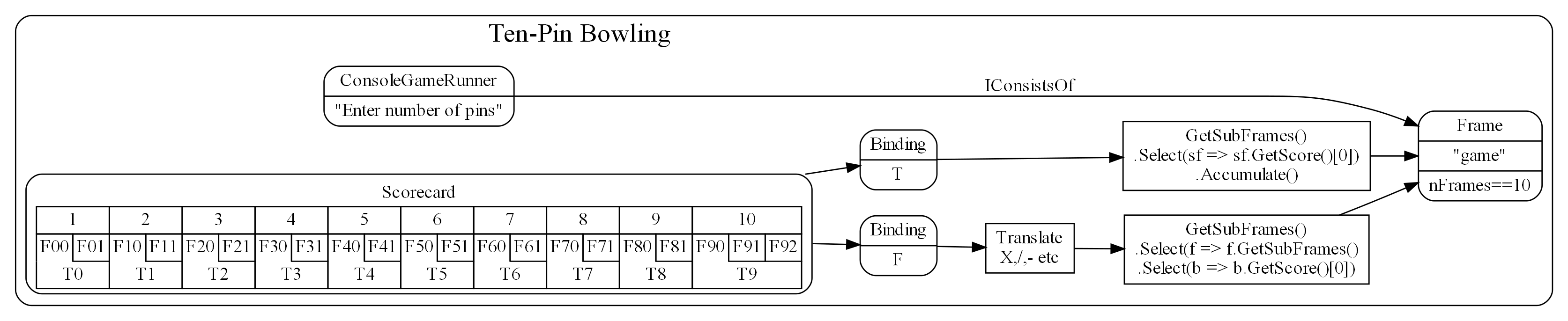
An abstraction we didn’t mention yet is the ConsoleGameRunner. Its job is to prompt for a score from each play, display the ASCII scoreboard, and repeat until the game completes.
The 'game' instance of the Frame abstraction on the right of the diagrams is the scoring engine we developed in Chapter Two. Together with this engine, we now have a complete application.
The rounded boxes in the diagram are instances of domain abstractions as usual for ALA diagrams. The sharp corner boxes are instances of Application layer abstractions. They are the mentioned functions for the Bindings. That code is application specific so goes in the application layer. They just do a simple query on the scoring engine.
Now tranlate the diagram into code. Here is the entire application layer code for ten-pin:
consolerunner = new ConsoleGameRunner("Enter number pins:", (pins, engine) => engine.Ball(0, pins))
.WireTo(game)
.WireTo(new Scorecard(
"-------------------------------------------------------------------------------------\n" +
"|F00|F01|F10|F11|F20|F21|F30|F31|F40|F41|F50|F51|F60|F61|F70|F71|F80|F81|F90|F91|F92|\n" +
"|    ---+    ---+    ---+    ---+    ---+    ---+    ---+    ---+    ---+    ---+----\n" +
"|  T0-  |  T1-  |  T2-  |  T3-  |  T4-  |  T5-  |  T6-  |  T7-  |  T8-  |    T9-    |\n" +
"-------------------------------------------------------------------------------------\n")
.WireTo(new ScoreBinding<List<List<string>>>("F",
    () => TranslateFrameScores(
        game.GetSubFrames().Select(f => f.GetSubFrames().Select(b => b.GetScore()[0]).ToList()).ToList())))
.WireTo(new ScoreBinding<List<int>>("T",
    () => game.GetSubFrames().Select(sf => sf.GetScore()[0]).Accumulate().ToList()))
);
If you compare this code with the diagram, you will see a pretty direct correspondence. Remember 'game' is the reference to the scoring engine project in the previous chapter.
That’s pretty much all the code in the application. Oh there is the 'translate' function, but it is pretty straight forward once you know the way a ten-pin scorecard works. For completeness here it is.
/// <summary>
/// Translate a ten-pin frame score such as 0,10 to X, / and - e.g. "-","X".
/// </summary>
/// <example>
/// 7,2 -> "7","2"
/// 7,0 -> "7","-"
/// -,3 -> "-","7"
/// 7,3 -> "7","/"
/// 10,0 -> "",X
/// 0,10 -> "-","/"
/// additional ninth frame translations:
/// 10,0 -> "X","-"
/// 7,3,2 -> "7","/","2"
/// 10,7,3 -> "X","7","/"
/// 0,10,10 -> "-","/","X"
/// 10,10,10 -> "X","X","X"
/// </example>
/// <param name="frames">
/// The parameter, frames, is a list of frames, each with a list of integers between 0 and 10 for the numbers of pins.
/// </param>
/// <returns>
/// return value will be exactly the same structure as the parameter but with strings instead of ints
/// </returns>
/// <remarks>
/// This function is an abstraction  (does not refer to local variables or have side effects)
/// </remarks>
private List<List<string>> TranslateFrameScores(List<List<int>> frames)
{
    // This function looks a bit daunting but actually it just methodically makes the above example tranlations of the frame pin scores
    List<List<string>> rv = new List<List<string>>();
    int frameNumber = 0;
    foreach (List<int> frame in frames)
    {
        var frameScoring = new List<string>();
        if (frame.Count > 0)
        {
            // The first 9 frames position the X in the second box on a real scorecard - handle this case separately
            if (frameNumber<9 && frame[0] == 10)
            {
                frameScoring.Add("");
                frameScoring.Add("X");
            }
            else
            {
                int ballNumber = 0;
                foreach (int pins in frame)
                {
                    if (pins == 0)
                    {
                        frameScoring.Add("-");
                    }
                    else
                    if (ballNumber>0 && frame[ballNumber]+frame[ballNumber-1] == 10)
                    {
                        frameScoring.Add(@"/");
                    }
                    else
                    if (pins == 10)
                    {
                        frameScoring.Add("X");
                    }
                    else
                    {
                        frameScoring.Add(pins.ToString());
                    }
                    ballNumber++;
                }

            }
        }
        rv.Add(frameScoring);
        frameNumber++;
    }
    return rv;
}
6.28.2. Tennis
So now that we have these domain abstractions for doing console game scoring applications, let’s do tennis:
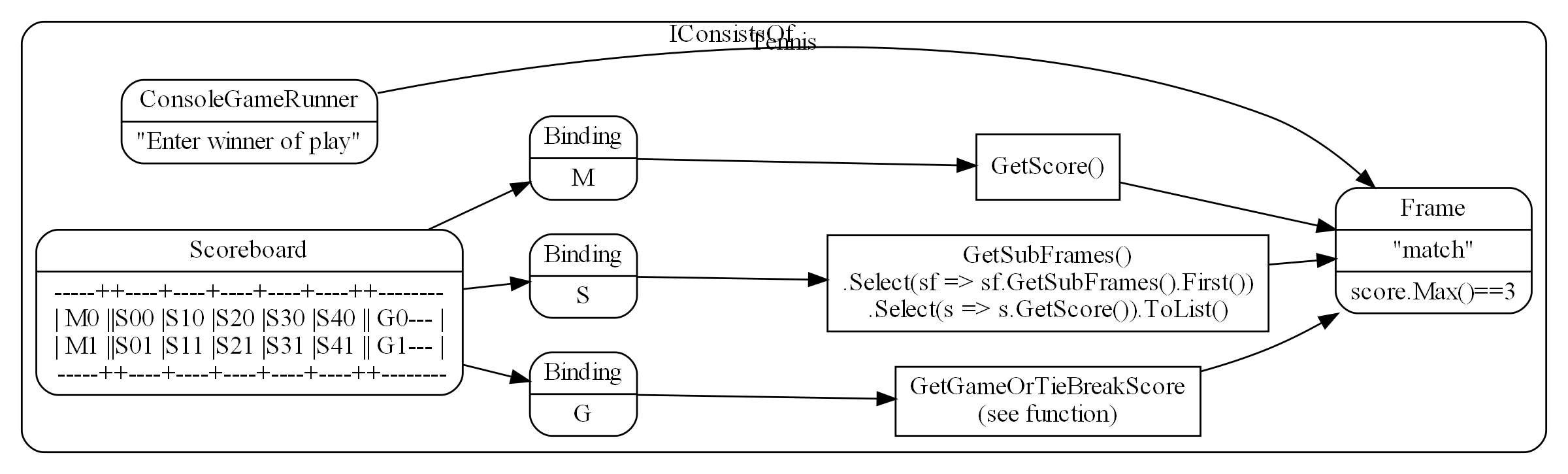
I left the code out of the GetGameOrTieBreakScore box as it is a little big for the diagram here. It is similar to the other queries but it must first determine if a tie break is in progress and get that if so. Also it translates game scores from like 1,0 to "15","love".
And here is the code for the Tennis diagram:
consolerunner = new ConsoleGameRunner("Enter winner 0 or 1", (winner, engine) => engine.Ball(winner, 1))
.WireTo(match)
.WireTo(new Scorecard(
        "--------------------------------------------\n" +
        "| M0  |S00|S10|S20|S30|S40|S50|S60|  G0--- |\n" +
        "| M1  |S01|S11|S21|S31|S41|S51|S61|  G1--- |\n" +
        "--------------------------------------------\n")
    .WireTo(new ScoreBinding<int[]>("M", () => match.GetScore()))
    .WireTo(new ScoreBinding<List<int[]>>("S", () =>
        match.GetSubFrames()
            .Select(sf => sf.GetSubFrames().First())
            .Select(s => s.GetScore())
            .ToList())
    .WireTo(new ScoreBinding<string[]>("G", () => GetGameOrTiebreakScore(match)))
);
If you compare this code with the diagram, you can see a pretty direct correspondence. match comes from the scoring engine project in Chapter two.
6.28.3. Concluding notes
Although the diagrams must be turned into text code to actually execute, it is important in ALA to do these architecture design diagrams first. They not only give you the application, they give you the architectural design by giving you the domain abstractions and programming paradigms as well. If you try to design an ALA structure in your head while you write it directly in code, you will get terribly confused and make a mess. Using UML class diagrams will make it even worse. Code at different abstraction levels will end up everywhere, and run-time dependencies will abound. Our programming languages, and the UML Class diagram, are just not designed to support abstraction layered thinking - it is too easy to add bad dependencies (function calls or 'new' keywords) into code in the wrong places.
Note that at run-time, not all dataflows have to go directly between wired up instances of domain abstractions. The data can come up into the application layer code, and then back down. This was the case when we did the functional composition example in Chapter One. In this application we are doing that with the code in the square boxes that get the score from the engine. The important thing is that all the code in the application is specific to the application requirements.
That completes our discussion of the console applications for ten-pin and tennis. The full project code can be viewed or downloaded here:
7. Chapter seven - The philosophy behind ALA
In this chapter we go into some of the deeper whys behind ALA. We did this somewhat in chapter three, but here we get more philosophical.
This chapter needs a review pass - some of thinking is out of date.
Once again each section of this chapter is a different perspective.
7.1. The human brain
In this perspective of ALA, we look at the problem of complexity in software in the context of how the human brain works.
Software design involves our intelligence or brain power. Understandability, readability, complexity are all things very closely related to the brain. Yet in the field of software engineering we pay little attention to how the brain understands our complicated world in order to understand how we should do our software.
Our brains do it primarily through one mechanism which we have come to call 'abstraction'. We learn abstractions from the commonality of multiple examples, and we then use abstractions without those examples cluttering up the common notion that was learned.
Our ancestors could use a word like 'bring your spear' and it had a simple meaning to them only because all the detail and knowledge that went into building a spear was replaced with the abstraction 'spear'. Without the abstraction, the sentence would have had to be more like "bring the object that we made by joining the object we made by applying blows to the hard material we found at the place…, with the long material we cut in the place with the tall…, by tying it with the long grass material using the gooey stuff we found at the…". Even this sentence was only made possible by other abstractions: joining, material, blows, hard, long (twice), cut, tall, tying, gooey, and found. If we expanded all of them until we were only using a few basic concepts like 'object' and 'place', we would have a sentence so long that we could never communicate at all. That’s what abstractions do, and how our brains make use of them. The word spear, in turn can be used to create a new abstraction, a hunting plan, while all of that other detail remains hidden from that new context.
The problem with software engineering is we are not making use of this way that the brain works. Simply put, we are not creating good abstractions. This lets the complexity inside one 'module' spill out into other modules. Abstractions, not modules, are the only mechanism that allows us to hide details at design-time.

As software engineers we do learn and use many abstractions. For example if we want to protect simultaneous access to the resource, our brain should conjure up 'mutex'.
If the brain already 'knows about' an abstraction, the abstraction is like any other single line of code, such as a mutex. We can make use of a mutex without having to deal with the details and complexities of how it works. We don’t have to think about the fact that we may have to wait for the resource. Nor that another thread may start running if we have to wait. Nor that if a higher priority thread preempts us while we have the resource, we may have it for a long time. Nor that if a still higher priority thread needs it during that long time, we will be given temporary priority to finish our use of it. We can just simply use the abstraction for protecting a resource.
Abstractions like mutex, regex, SQL are already invented by the 'culture' of software engineering, much like memes in the real world have been passed down to us. Where we fall down is when we get into a particular domain where the abstractions have not yet been invented, and we need to invent them. It is not easy to invent new abstractions, but invent them we must, at a rate far higher than is normal for cultural evolution.
Good domain abstractions, introduced and learned by new developers in the domain, then appear to them as normal program elements - things they can use with extraordinary convenience like any other line of code.
7.2. Abstraction
Of the overwhelming list of engineering topics that we listed in Chapter One, this topic that is the most fundamental to ALA, and the one most needed for explaining it. It’s also probably the vaguest and most misunderstood topic in software engineering, so we will spend some time understanding it.
Abstraction will be the king. The short reason why we start with abstraction is that our quality attributes, complexity and understandability are very much to do with how our brains work, and for 100,000 years at least, our brains have worked with abstractions to understand our world. Abstractions are the only mechanism our brains use for dealing with otherwise complex things.
As in a chess game, winning is only about protecting the king. But this Abstraction king is benevolent. If he is destroyed, you do not lose the game immediately. It will take time, but you will lose.
There are other contenders to be king in the engineering topics list. For example, it is said that the best thing about TDD is not the testing but the emergence of better abstractions. TDD is like a lord that serves the king. It usually serves the king, causing you to make better abstractions. But sometimes it just serves its own purpose and makes the abstraction worse. It just produces code that works where it passes and no more.
Another contender is microservices. It is popular because it improves your abstractions by making them harder to destroy with cross coupling. But it too is just a lord. Because it provides physical boundaries that in normal software would be crossed, it serves the king. But by serving the abstraction king directly we can have logical boundaries, and all their benefits, even in 'monolithic' code.
Another contender to be king is 'no side effects' used by the functional mathematical purity guys. There are those who talk as if disobeying this king is absolute treason. But again, this lord is only effective because he usually serves the abstraction king. But, again, there are times when he doesn’t, and 'no side effects' is not enough to make a good abstraction.
ALA always follows the one true king.
7.2.1. Classes, Modules, functions and encapsulation.
Classes, Modules, functions and encapsulation are artefacts of the language and do their thing at compile-time. They are not necessarily abstractions. They have been around for about 60 years, not enough time for our brains to see them in the same way as the compiler does. Although abstractions are implemented using these artefacts, ALA needs them to also be abstractions. In ALA "abstraction" is the term we use for the artefacts of our design instead of classes, modules, functions, or components, all of which are extremely fragile as abstractions.
In ALA, classes can still be used inside an abstraction, but they are just a language construct to allow operations given a reference to an object, not to so much to associated data and methods, or to encapsulate data representation. Inside an abstraction everything is considered cohesive, not structured in any way. Classes don’t make the abstractions in themselves, although in ALA many abstractions are implemented using a single class with ports.
7.2.2. Wikipedia on abstraction
"Thinking in abstractions is considered by anthropologists, archaeologists, and sociologists to be one of the key traits in modern human behaviour, which is believed to have developed between 50 000 and 100 000 years ago. Its development is likely to have been closely connected with the development of human language, which (whether spoken or written) appears to both involve and facilitate abstract thinking."
In the real world, new abstractions come along infrequently, and are conceived of by few. People quickly begin using them to understand new insights or compose new things. They become so natural to us that we forget that they are abstractions. In no other field do we need to create them as fast as in software engineering. It is the most important skill a developer needs to have.
7.2.3. Defining abstraction
The term abstraction is arguably one of software engineering’s vaguest or most overloaded terms. Because it is the most fundamental concept in ALA, we try to provide a definition. I find the easiest way to define it is to provide a set of 'statements about', 'properties of', or 'what it is nots':
-
Etymology: 'to draw out commonality'
-
The concept or notion drawn out of what is common in multiple instances
-
Because it is a 'commonality', it is inherently reusable. Kruger says that abstraction and reuse are two sides of the same coin.
-
Has inherent stability - as stable as the concept itself
-
The only mechanism that separates and hides design-time knowledge
-
Its concept or notion is easier to remember than its implementation. For a good abstraction, it is much, much simpler.
-
Abstractness increases with scope of reuse
-
Knows nothing about peer abstractions
-
use ports (instances or interfaces) for IO instead of directly calling other abstractions.
-
Abstractness decreases with more ports
-
Abstractness decreases as you get closer to your specific application
-
Abstractness is not how far you are above physical hardware
-
An ability our brains evolved understand the world
-
The only way we have of dealing with complexity
7.2.4. Leaky abstractions
The code inside abstraction A could potentially tell how long B takes to execute. If it is sensitive to that, this is not a problem with ALA, but with the leaky abstraction. The design needs to be changed to eliminate the dependency on that leakage, or, if that is not possible, the coupling managed. But for the vast majority of code, the coupling between the insides of any two abstractions really is zero.
7.2.5. The three stages of creativity
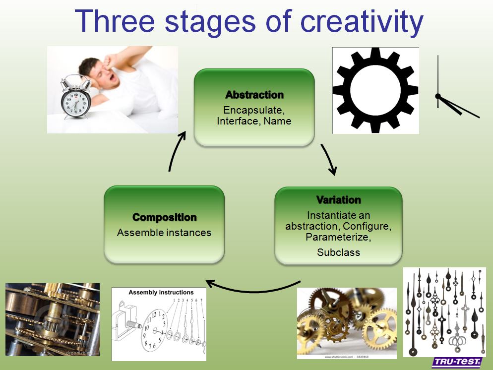
A good abstraction separates the knowledge of different worlds. A clock is a good abstraction. On one side is the world of cog wheels. On the other side is someone trying to be on time in their busy daily schedule. Neither knows anything about the details of the other. SQL is another good abstraction. On one side is the world of fast indexing algorithms. On the other is finding all the orders for a particular customer. Let us consider a domain abstraction - the calculation of loan repayments. On one side is the world of mathematics with the derivation and implementation of a formula. On the other, the code is about a person wanting to know if they can afford to buy a house. If your abstractions don’t separate knowledge of different worlds like this, then you are probably just factoring common code. Find the abstraction in that common code. Make it hide something complicated that’s really easy to use and really useful, like a clock.
The creativity cycle starts with abstractions, such as cogs and hands, instantiates them, configures them for a particular use, then composes them into a new abstraction. In ALA we usually go around the creativity cycle three times, creating three layers on top of our base programming language.
7.2.6. Abstractions need ports
In traditional programs, inputs (or at least incoming function calls) are typically part of the module or class’s interface but outputs (or at least outgoing function calls) are typically just buried in the code.
This is fine if calling functions or methods in a lower abstraction layer. However, it is absolutely not fine if calling functions or methods of a peer in the same abstraction layer.
In ALA all inputs and outputs to or from peers in the same layer must be 'ports'. There should be one port for each peer that can be wired. This is the Interface Segregation Principle. A port is a logical wirable connection point. A port either implements or accepts an interface. Outgoing function calls buried in the code that at run-time will go to a peer must only go to the port, which has an indirection mechanism of some kind.
Programming languages encourage all outgoing function or method calls to refer directly to the destination, or the destination’s interface, so you have to make an effort to avoid doing this.
A port is not an artefact of programming languages (yet) so they must be implemented logically somehow as normal code. To code a logical port, you need to do two things.
-
The interface type of the port must not be owned by another peer abstraction. The interface type must be from a lower abstraction layer.
-
The name of the port is the name of the field that accepts the interface.
A port can have multiple interfaces. In this case I make the names of the multiple fields contain the port name.
If you are using an asynchronous event driven design, the equivalent of a conventional outgoing function call is typically written something like this:
Send(Event, Receiver, Priority);
where the Event is something the receiver defines.
Again, we are sending the event directly to a peer abstraction using the peer abstraction’s interface (its event).
In ALA, sending an event should be self-oriented, so written something like this:
Send(Sender, SenderPort)
The sender just sends the event out, not knowing where it goes, and the port identifies the event (or you could have both port and event). This just tells the event framework who the sender and sender’s port was. The event framework gets information from the application in the top layer to know what to do with the event. The application has the specific knowledge to know what an event from a given sender on a given port means, and therefore where it should go, and what the priority should be.
In general, classes, modules, components, functions should all have ports for both input and output. They should not own the interface types for these ports, whether they are incoming or outgoing.
An output port from an abstraction may say 'This has happened' or 'Here is my result', not 'do this next', or 'here is your input'.
There are multiple ways to implement the indirection inherent in ports for outgoing calls. They can be callbacks, signals & slots, dependency injection, or calls to a framework send function.
Note that inputs and outputs are not necessarily on different ports. We may want to wire both inputs and outputs between two instances or two abstractions with a single wiring operation. The general case is that a single wiring operation wires multiple interfaces that are logically one port. One contains methods going in one direction and the other contains methods going in the other.
7.3. Complexity
7.3.2. Dijkstra on complexity
"It has been suggested that there is some kind of law of nature telling us that the amount of intellectual effort needed grows with the square of program length. But, thank goodness, no one has been able to prove this law. And this is because it need not be true. We all know that the only mental tool by means of which a very finite piece of reasoning can cover a myriad cases is called “abstraction”; as a result the effective exploitation of his powers of abstraction must be regarded as one of the most vital activities of a competent programmer. In this connection it might be worth-while to point out that the purpose of abstracting is not to be vague, but to create a new semantic level in which one can be absolutely precise. Of course I have tried to find a fundamental cause that would prevent our abstraction mechanisms from being sufficiently effective. But no matter how hard I tried, I did not find such a cause. As a result I tend to the assumption —up till now not disproved by experience— that by suitable application of our powers of abstraction, the intellectual effort needed to conceive or to understand a program need not grow more than proportional to program length."
The "conceive" part I agree with, if by that we mean the development. However, the "intellectual effort to understand" part needs further insight. We shouldn’t have to read an entire program to understand a part of it. We ought to be able to understand any one part of it in isolation. The effort to read any one part should be approximately constant. In Chapter One of this book there was a quality graph of complexity here.
These graphs are qualitative in nature, based on experience. But now that we have a better understanding of ALA structure, we can explain how it manages to keep complexity from increasing.
In ALA, the design-time view of the system is nothing more than a static view of instances of abstractions composed together. In a typical application, there will be of the order of fifty different domain abstractions - not a difficult number to familiarize yourself with in a new domain.
Abstractions have no relationship with one another. Each is a standalone entity like a standalone program. If every abstraction contains say 500 lines of code, and the system itself contains 500 lines (instances of abstractions wired together) then the most complex the software gets is that of 500 lines of code.
Even if one abstraction is overly complex internally, say it conceals a piece of legacy code using a facade pattern, that doesn’t affect the complexity of any other part of the system.
ALA is based on the realization that abstraction is fundamentally the only mechanism available to us to achieve this constant complexity.
When doing this for the first time in a domain, it’s not easy to invent the abstractions. but the alternative is always runaway complexity.
|
The goal of software architecture should be to keep complexity constant. |
7.4. Zero coupling, not loose Coupling
Here we meet the first meme from our list of software engineering topics that we must throw out. To many, this will seem a surprising one. Yes, I am saying 'loose coupling' is undesirable.
7.4.1. A common argument
An argument is sometimes stated along these lines: "There must be at least some coupling, otherwise the system wouldn’t do anything." Hence we have the common meme about "loose coupling and high cohesion". In this section we show how this argument is false and resolve the apparent dilemma. We will eliminate all forms of design-time coupling except one. That one remaining one is anything but loose and very desirable.
7.4.2. Classifying coupling
Think of some instances of dependencies you know of in a system and try to classify them into these three types by asking when the system would fail without it.
For example, let’s say that dataflows from an ADC (analog to digital converter) to a display as part of a digital thermometer. At run-time, both must exist. At compile-time both must have the same method signature:

Or the display may tell the ADC when to do the conversion. At run-time there is temporal coupling.
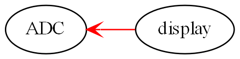
In this one there is an association from a Customer class to an Account class to facilitate communication between them. At run-time there is coupling. At compile-time there is coupling too - the type of the Account class must be exactly the same as expected by the Customer class:
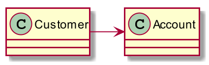
In all the above diagrams, relationships shown in red indicate they are disallowed by the ALA constraints. Green is for desirable relationships, of which there is only one. When we disallow all these types of coupling, the modules, components, functions and classes can now be abstractions.
7.4.3. Run-time, Compile-time and Design-time
A few times already in the article, I have sneaked in a magic qualifier, 'design-time'. You know how we sometimes talk about run-time and compile-time with reference to binding. In ALA we recognise that understandability, complexity, etc, are all happening at design-time. By design-time I mean any time you are reading code, writing code, or changing code.
At run-time, the CPU processes data. At compile-time, the compiler processes code. At design-time the brain is processing abstractions.
In conventional code, it is common for all forms of coupling, run-time, compile-time, and design-time, to appear as coupling between modules or classes.
You can work out what type of dependency you have by when it first breaks. A run-time dependency doesn’t break until the program runs. The program can still be compiled and it can still be understood.
A compile-time dependency first breaks at compile-time. At design-time the code can still be understandable.
A design-time dependency prevents code from even being understood. The code loses its meaning.
7.4.4. Layers
In everyday design, knowledge dependencies are not normally shown as lines. You simply use the abstraction by its name. But in this article, just so we can explain the meta-architecture, we will sometimes draw knowledge dependencies like this (always downward).
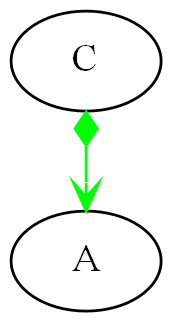
This represents that the implementation of abstraction C knows about abstraction A. A is more abstract than C. C and A cannot therefore be peers, as was the case with the components above. Peer abstractions cannot have any coupling with one another.
7.4.5. Whole-Part pattern
If you are familiar with the Whole-Part pattern, ALA uses it extensively. But there is a constraint. The Whole-Part pattern is only used with knowledge dependencies (since that is the only relationship you are allowed). It may of course be used in other forms inside an abstraction, provided it is completely contained in a single abstraction.
A real world example of the Whole-Part Pattern with knowledge dependencies is Molecules and Atoms. A water molecule, for example, is the whole.
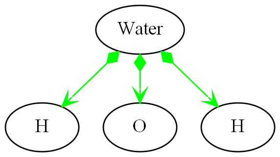
Oxygen and hydrogen are the parts. Note that oxygen and hydrogen are abstractions, and they are more abstract than water because they are more ubiquitous, more reusable and more stable (as a concept) than any specific molecule. We could make a different molecule but still use exactly the same oxygen and hydrogen as parts to compose the new molecule.
| When we use the word 'ubiquitous', it refers to the number of times the abstraction is used in a Whole-Part pattern to make other abstractions. It doesn’t refer to the number of abstractions that are instantiated. So just because there is a lot of water, that doesn’t make the abstraction ubiquitous. In comparing the abstraction levels of Oxygen and Hydrogen with water, Oxygen and Hydrogen are more ubiquitous because they are used to make more abstractions than water is. |
The molecules and atoms analogy with ALA is very close, and we will return to it when we come to explain in more detail how run-time and compiler-time dependencies are moved inside a single abstraction.
For now we just need to remember that we are using the whole-part pattern with knowledge dependencies only. At design-time, the whole is explained and reasoned about in terms of the parts, just as the water molecule is in terms of the oxygen and hydrogen.
7.4.6. Run-time/design-time congruence
A software program can be temporally confusing. Everything that happens at design-time is in preparation for what will happen at run-time. Our low-level imperative languages tend to keep the two congruent. The statements in the program at design-time follow in the same order as they will execute at run-time. The only difference between the two is a time shift and the speeding up of the clock.
When we want the knowledge of run-time dependencies to be moved inside another abstraction, this congruence between design-time and run-time must be broken. Unfortunately, developers start out by learning a low-level imperative language, so it becomes unnatural to them to architect their programs without this congruence. Indeed, breaking this congruence needs a pattern to be learned, and then carefully protected from the temptations of our imperative languages. I call it the Ẃiring pattern'.
Before going into the pattern, we need to round out the most important aspects of ALA.
7.5. Wiring pattern - Part one
We now introduce the pattern that both solves the congruence problem just discussed in the previous section, and provides the alternative to all those disallowed coupling types discussed earlier. This pattern is usually an important part of ALA.
Note: The wiring pattern is not necessarily a part of an ALA architecture. For example, if your whole problem is just an algorithm, and therefore suits a functional programming style, then you can still compose abstractions with function abstractions, provided all function calls are knowledge dependencies, and not say, just passing data or events.
If you are using monads, especially I/O monads, or RX (reactive extensions), especially with hot observables, you are already using the wiring pattern. The pipes and filter pattern is also an example of the wiring pattern. Labview or Node-Red can use the wiring pattern. There are many other examples of the wiring pattern. Most support a dataflow programming paradigm. Here we generalise the pattern to support any programming paradigm.
The wiring pattern may be the same as the "Component Pattern" in some literature if used with what is referred to as 'configurable modularity' or 'abstracted interactions'.
The wiring pattern allows lines on your application diagram to mean any programming paradigm you want that express your requirements. It also allows you to implement multiple programming paradigms together in the same diagram.
If you are using dependency injection with explicit code for the wiring (not auto-wiring), then you are half way there.
The wiring pattern separates design-time/run-time congruence. It works by having a 'wiring-time' that is separated from run-time. 'Wiring-time' can happen any time before run-time. It can happen immediately before it, as for instance in LINQ statements or RX with a cold observable. It becomes powerful when we make wiring-time congruent with design-time. Usually the wiring code will actually run at initialization time, when the program first starts running. That initialization code becomes the architectural design.
Let’s suppose you have designed your system with two modules, A and B. There will be one of each in your system.
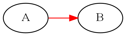
At run-time we know that A will talk to B. So we design A to have an association with B. The association may first appear on a UML model, or it may go straight into the code something like this:
static component A
{
   B_method();
}
static component B
{
   public B_method() { }
}
A and B may be implemented as non-static, with only one instance of each. The association is still there.
component A
{
   private var b = new B();
   b.method();
}
component B
{
   public method() { }
}
A may create B itself, which is a composition relationship, as above. Or A may have a local variable of type B passed in by some kind of dependency injection, which is still an association relationship.
component A
{
   B b;
   public setter(B _b) {b = _b}
   b.method();
}
Note that although dependency injection was used, it only eliminated part of the dependency, that of which particular subtype of B it is going to talk to, but A still knows the general type B, which is not allowed in ALA. (Part of the problem here is that A and B were probably arrived at by decomposition, and so they have subtle knowledge of each other, for example of how they collaborate.)
If A and B are collaborating, they are not abstractions. Their knowledge of each other at design-time (to enable their relationship at run-time) binds them to each other so that neither can be reused in any other way. And if they can’t be reused, they can’t be abstract.
Let’s revisit the water molecule analogy we discussed earlier for the Whole-Part pattern, and develop it further to be clearer how these dependencies affect abstractions. Let’s say we have decomposed water into two components, Oxygen and Hydrogen. Oxygen will talk to Hydrogen to get an electron, so we write:
component Oxygen
{
   var h1 = new Hydrogen();
   var h2 = new Hydrogen();
   h1.getElectron();
   h2.getElectron();
}
The diagram for that looks like this:
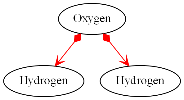
In the real world, oxygen is a very useful abstraction for making other molecules. In writing code this way to make water, we have tied it to hydrogen. Oxygen can’t be used anywhere else, at least not without bringing with it two hydrogens, rendering it useless. By implementing the Oxygen-Hydrogen relationship needed to make water in oxygen, we have destroyed the oxygen abstraction. We never even made the water abstraction. To understand water, we would have to read the code inside oxygen, where the parts about water have become entangled with the inner workings of oxygen, protons and neutrons and all that stuff. Oxygen is also used to make caffeine. We could never make coffee!
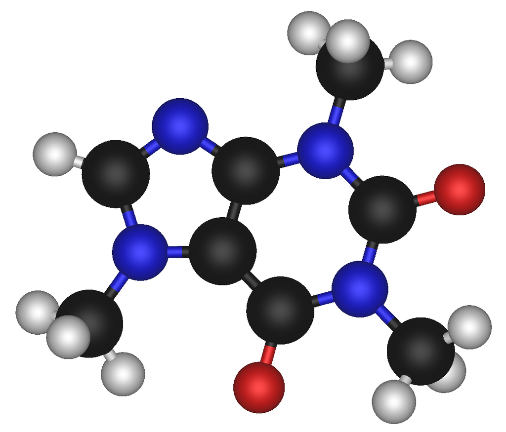
Abstractions are fragile and get destroyed easily, so we have to take care to protect them. What we needed to do was to put the knowledge about the relationship between oxygen and hydrogen to make water in a new abstraction called Water.
In general, to break coupling between peer modules A and B, we move the knowledge of the coupling to a higher level abstraction (less abstract level) where it belongs. Let’s call it C. C is a more specific abstraction. The knowledge is encapsulated there - it never appears as a dependency of any kind. And it is cohesive with other knowledge that may be contained inside abstraction C.

becomes
The diagram above is only to show the ALA knowledge dependency relationships between the three abstractions. It doesn’t yet show explicitly that an instance of Abstraction A will be wired to an instance of Abstraction B. In practice we never actually draw knowledge dependencies. We are just doing so here to show how ALA works. We would draw it in this way instead:

Now we have the explicit wiring. It looks a lot like the original diagram where we had no C. But where the knowledge is coded is very different. Because it is C and not A that has the knowledge of the relationship between A and B, Abstractions A and B do not change. They continue to know nothing of the connection. They remain abstractions. They remain re-usable.
It may seem at first that adding the extra entity C is a cost, but in fact C is an asset. It shows the structure of the system. It shows it explicitly. It shows it in one small understandable place. And it is executable - it is not a model.
The original abstractions were left below C to show that they still exist as free abstractions to be used elsewhere. They are not contained by C in any way as modules from a decomposition process would be. The A and B inside C are only instances. We wouldn’t normally bother to draw the abstractions below. So we just draw this:
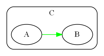
C must achieve the connection between A and B either at compile-time or run-time. With current languages, the easiest time to do this is at initialization time, when the program first starts running. This is similar to dependency injection, except that we are not going to inject the instance of B into A.
This is what the code inside C might look like:
Abstraction C
{
var a = new A();
var b = new B();
a.wireTo(b);
}
Typically we will write the code using the fluent pattern, with the wireTo method always returning the object on which it is called, or the wireIn method always returning the object wired to. The constructor already returns the created object by default.
Abstraction C
{
new A().wireTo(new B());
}
If A and B are static modules, this produces something like:
Abstraction C
{
A_setcallback(B_method);
}
7.6. Wiring pattern - part two
We are half-way through explaining the wiring pattern. Now we turn our attention to how A and B can communicate without knowing anything about each other.
This part of the pattern is also called "Abstract Interactions"
Of course, one way is that C acts as the intermediary. This way is less preferred because it adds to C’s responsibilities. But it is sometimes necessary if there are some abstractions brought in from outside. Such abstractions will 'own' their own interfaces or may come with a contract which C will have to know about. C will usually have to wire in an adapter, or handle the communications between the two abstractions itself.
A better way, because it leads to an architectural property of composability, is that A and B know about a 4th abstraction that is more abstract than either of them. This is legal because it is a design-time knowledge dependency. Let’s call it I.
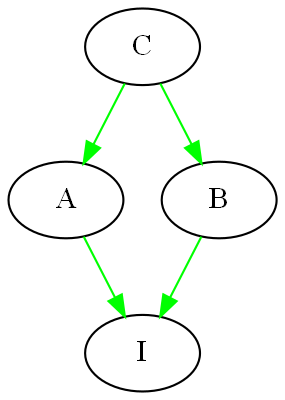
I is an interface of some kind. It may or may not be an actual artefact. What it must be is knowledge that is more abstract than A and B and therefore knows nothing of A and B. It is more ubiquitous and more reusable than A and B are. In other words we can’t just design I to meet the particular communication needs of A and B. That would cause A and B to have some form of coupling or collaboration with each other, and again destroy them as abstractions.
I is so abstract, ubiquitous and reusable, that it corresponds to the concept of a programming paradigm. We will cover programming paradigm abstractions in following sections because they are a critically important part of ALA. We will see that ALA is polyglot with respect to programming paradigms.
Returning to a software example, let’s choose a single simple programming paradigm: activity flow. This programming paradigm is the same as the UML Activity diagram. When we wire A to B and they use this paradigm, it means that B starts after A finishes. If A and B accept and provide this interface respectively, then wiring them together by drawing an arrow will have that meaning, and cause that to happen at run-time.
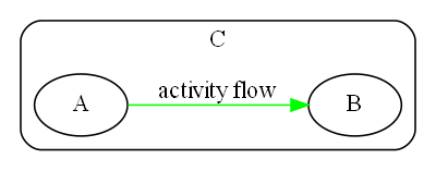
It is easy to create an interface for the activity-flow programming paradigm. It has a single method, let’s call it 'start'. Many abstractions at the level of A and B can either provide or accept this paradigm interface. Then instances of them can be wired up in any order and they will follow in sequence just like an Activity diagram.
Note that the Activity Diagram is not necessarily imperative in that any Activity can take an amount of time to complete that is not congruent with the actual CPU execution of code. In other words activities can be asynchronous with the underlying code execution, and for example, delay themselves during their execution, or wait for something else to finish, etc.
The code in Abstraction A could look something like this. Don’t take too much notice of the exact method used to accomplish the wiring. There are many ways to do this using only knowledge dependencies. The important thing is that A continues to know nothing about its peers, continues to be an abstraction, and yet can be wired with its peers to take part in any specific activity flow sequence:
Abstraction A : IActivity
{
private IActivity next = null;
public IActivity wireTo(IActivity _next)
{
next = _next;
return _next;
}
IActivty.start()
{
// start work
}
// code that runs when work is finished.
// may be called from the end of start, or any time later
private finishedWork()
{
if (next!=null) next.start();
}
}
Abstraction A both provides and accepts the interface. This allows it to be wired before or after any of its peer abstractions. In ALA we use the word 'accepts' rather than 'requires' because there is often an end to a chain of abstraction instances wired together. If no next interface is wired in, the activity flow ends.
Abstraction B would be written in the same way, as it also knows about the Activity flow interface:
Abstraction B : IActivity
{
private IActivity next = null;
public IActivity wireTo(IActivity _next)
{
next = _next;
return _next;
}
IActivty.start()
{
// start work
}
// code that runs when work is finished.
// may be called from the end of start, or asychronously later
private finishedWork()
{
if (next!=null) next.start();
}
}
| As an aside, in C# projects, we wrote wireTo as an extension method for all objects. It used reflection to look at the private interface variables in the source class and the interfaces provided by the destination class. It would then match up the interface types and do the wiring automatically. It could even use port names to explicitly wire ports of the same types. |
Now let’s revisit the molecule analogy. By now we would know to put the knowledge that Oxygen is bonded to two Hydrogens inside the water abstraction where it belongs.
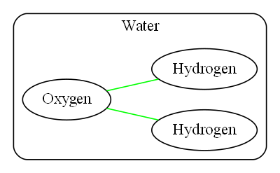
In terms of knowledge dependencies it means this:
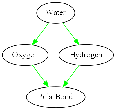
The programming paradigm here is a polar bond. It is more abstract (more ubiquitous and reusable) than any particular atom. We could have a second programming paradigm, a covalent bond, as well. Again, the important thing here is not what the code does - that is arbitrary (and not actually correct chemistry) but how the atoms can be made to interact while retaining their abstract properties with only design-time knowledge dependencies:
Abstraction PolarBond
{
GiveElectron();
}
Abstraction Oxygen
{
private PolarBond hole1 = null;
private PolarBond hole2 = null;
public Oxygen wireIn(PolarBond _pb)
{
if (hole1==null) hole1 = _pb; else
if (hole2==null) hole2 = _pb;
return this;
}
public Initialize()
{
if (hole1!=null) { hole1.getElectron(); BecomeNegativelyCharged(); }
if (hole2!=null) { hole2.getElectron(); BecomeNegativelyCharged(); }
}
}
Abstraction Hydrogen : PolarBond
{
PolarBond.getElectron()
{
BecomePositivelyCharged();
}
}
Abstraction Water
{
new Oxygen()
.wireTo(new Hydrogen())
.wireTo(new Hydrogen())
.Initialize();
}
Let’s do one more example, this time with a dataflow programming paradigm. I have found that dataflow is the most useful programming paradigm in practice. It is useful in a a large range of problems.
Let’s construct a thermometer. Assume we already have in our domain several useful abstractions: an ADC (Analog Digital Converter) that knows how to read data from the outside world, a Thermistor abstraction that knows how to linearise a thermistor, a Scale abstraction that knows how to offset and scale data, a filter abstraction that knows how to smooth data, and a display abstraction that knows how to display data.
All these domain abstractions will use the dataflow programming paradigm. Note that none of them know anything about a Thermometer, nor the meaning of the data they process.
So we can go ahead and create a Thermometer application just by doing this:
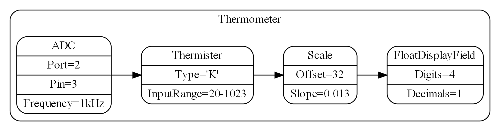
Note that we configure all the abstraction instances for use in the Thermometer by adding configuration information into rows on the instances.
When we manually compile the diagram (assuming we don’t have automated code generation), it might look something like this (again using fluent coding style):
Abstraction Thermometer
{
new ADC(Port2, Pin3)
.setFrequency(1000)
.wireTo(new Thermister().setType('K').setInputRange(20,1023)
.wireTo(new Scale(32,0.013)
.wireTo(newDisplay().setDigits(4).setDecimals(1))
)
);
}
| The configuration setters and the WireTo extension method return the object on which the call is made to support the fluent coding style. |
The diagram is the requirements, the solution and the architecture of the application, and is executable. The diagram has all the cohesive knowledge that is a thermometer, and no other knowledge.
The diagram can be read stand-alone, because all the dependencies in it are knowledge dependencies on abstractions we would already know in the domain.
Let’s say when the Thermometer runs, there is a performance issue in that the ADC is producing data at 1kHz, and we don’t need the display to be showing Temperatures at that rate. Also the temperature readings are noisy (jumping around). Let’s make a modification to the Thermometer by adding a filter to reduce the rate and the noise:
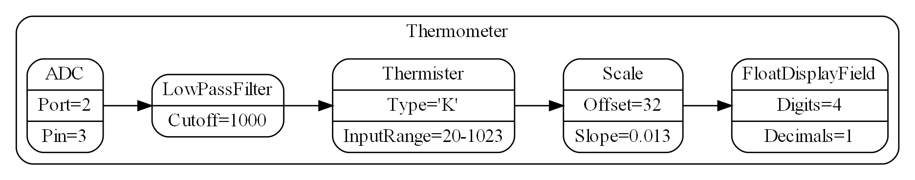
If the domain abstractions are not already implemented, we have got the architecture to the point where we can ask any developer to implement them, provided we first give them knowledge of ALA and of the programming paradigm(s) being used.
But let’s look how the dataflow paradigm might work.
| If you are familiar with RX (Reactive extensions) with a hot observable source (which is an example of the wiring pattern), this is similar in concept although RX tries to have duality with for-loops iterating through the data. The dataflow paradigm we set up here will just be a stream of data. The IDataFlow interface corresponds to IObserver, and the wireTo method corresponds to the Subscribe method. |
| The ideal would be a language where we don’t have to decide if the dataflow will be push or pull, synchronous or asynchronous, buffered or unbuffered or other characteristics of communications. The abstractions would not need to know these things - they would just have logical I/O ports, and the type of communications could be binded in at compile-time as part of the performance configuration of the system. |
| Later we will introduce an asynchronous (event driven) execution model. It is preferable to do the dataflow paradigm interface using that because it allows better performance of other parts of the system without resorting to threads. |
For simplicity, we will just implement a synchronous push system. Again, don’t worry about the filter itself. The code is just there to see how the LowPassFilter fits in with the dataflow programming paradigm, and how simple doing that can be.
Interface IDataFlow<T>
{
push(T data);
}
/// LowPassFilter is a DataFlow paradigm decorator to be used in an ALA archtecture.
/// 1. Decimates the incoming data rate down by the setCutoff configuration
/// 2. Smooths the data with a single pole filter with cutoff frequency equall to the input frequency divided by the cutoff. T must be a numeric type.
/// Normal checks and exceptions removed to simplify
Class LowPassFilter<T> : IDataFlow<T>
{
private Dataflow next;
// This is normally done by a general extension method
public IDataflow wireTo(IDataflow _next)
{
next = _next;
return _next;
}
integer cutoff;
setCutoff(integer _cutoff)
{
cutoff = _cutoff;
}
int count = 0;
T filterState = NAN;
IDataFlow.push(T newData)
{
if (filterState==NAN) filterState = newData * cutoff;
filterState = filterState - filterState/cutoff + newData;
count++;
if (count==cutoff)
{
count = 0;
if (next!=null) next.push(filterState/cutoff);
}
}
}
You will notice that both the Domain abstraction, Filter, and the Programming Paradigm abstract interface, IDataFlow, use a parameterised type. This makes sense because only the application, the Thermometer, knows the actual types it needs to use.
7.7. Expression of requirements
One of the fundamental aspects of ALA is that the abstraction level of the application is fixed and defined by:
|
The succinct description of requirements |
This is a similar concept to a DSL (but not quite the same). If the abstraction level were more specific, we wouldn’t have the versatility to describe changing requirements or new applications in the domain (too expressive). If it were were more general, we would have to write more code to describe the requirements (not expressive enough).
I noticed during 40 years of code bases written at our company, two did not deteriorate under maintenance. They always remained as easy to maintain as they were in the beginning, if not easier. All others deteriorated badly. Some deteriorated so badly that they could no longer be maintained at all. At the time we din’t know why and could not predict which way it would go. It seemed as if you just got lucky or unlucky.
Perhaps it was the type of changes that came along? But the two code bases that were easy to maintain seemed to be easy for any kinds of change. And the ones that were hard were hard for any change. This continued to hold for years on end. Of course, most changes were changes to requirements, but often enough, changes would be for performance or other reasons. These also seemed easy in these two code bases, but hard everywhere else.
I began to look at the structure and style of the easy and hard code. The easy code was not complicated while the hard code had degenerated well into the complex. The two easy code bases were doing very different things in very different ways, so there was apparently not a common structure or style. But they did have one thing in common. The code that represented the knowledge of the requirements was separated out. That code only described requirements, and it was expressed in terms of other things that were relatively independent, reusable and easy to understand (what we call abstractions).
This is what first gave rise to one of the core tenets in ALA. The first separation is not along the lines of functional or physical parts of the system, such as UI, Business logic, and Data model. The first separation is code that just describes requirements.
Of course this has a strong parallel with how DSLs work. Is ALA just DSLs? There are several differences. Firstly in ALA we don’t try to create a sandbox language for a domain expert to maintain applications. We don’t go as far as an external DSL. It’s for the developer and we don’t want to cut him off from the power he already has when it is needed. We just give him a way to organise the code and a process to get him there - describe the requirements knowledge in terms of abstractions and then trust that those abstractions, when written, will make it work.
7.8. No two modules know the meaning of data or a message.
The two modules will have collaborative knowledge. We reason that the sender must know the meaning to formulate the message, and the receiver must know the meaning to interpret the message. So how can it be avoided? The answer is to make the sender and receiver in same abstraction. They both know the same knowledge, so they are cohesive, so they should be together. In the logical view of the system, they are two instances of the one abstraction. We let the physical view fact that the sender and receiver will be deployed in different places drive them to be different modules.
7.9. Expressiveness
Requirements are usually understated initially in terms of abnormal conditions. However, they are usually communicated quite quickly relative to the time to write the code. In ALA, they are separately represented. The precise expression of the requirements using the right programming paradigms should take about the same amount of information as the English explanation of them.
In general, ALA probably requires about the same amount of total code. But once the requirements are represented, the domain abstractions are known and they are independent small programs with dependencies only on the programming paradigm interfaces used. This independence should make them much easier to write. As the system matures, the effort to modify gets less as more domain abstractions come on line as tested, mature and useful building blocks. The final cost of maintenance should be much less than an equivalent ball of mud architecture.
7.10. No models
|
Leave out details only inside abstractions |
It is generally accepted that a software architecture must, by necessity, leave out some details. Somehow we need to find a satisfactory architecture without considering all the details. Often models are used to represent the architecture. Like its metaphor in the real world, a model leaves out details. The problem is they can leave out arbitrary details. We can’t be sure that some omitted detail won’t turn out to be important to the architectural design.
ALA therefore does not use the model metaphor. Instead, it uses diagrams (if not plain old text). Of course, this distinction comes down to semantics. I define a diagram as different from a model in that it does not leave out details arbitrarily. The only way to leave out details in an ALA diagram is inside the boxes, in other words inside abstractions. Because abstractions already have the required meaning when used in the diagram, the details omitted can’t be important to the diagram, and can’t affect the architectural design.
7.10.1. Executable architecture
|
Your architecture should be executable |
The distinction between diagrams and models explained in the previous section gives rise to an interesting property of the ALA architecture. Diagrams are executable. Therefore the architecture itself will be executable. When the implementation of the abstractions is complete, there will be no work left to do to make the architecture execute (apart from practical considerations of bugs, misinterpretations of the requirements, performance issues, improvements to the initially conceived set of domain abstractions, and the like).
There should be two aspects of an architecture, the meta-architecture and the specific architecture. If using ALA, ALA itself is the meta-architecture and the top level application diagram is the specific architecture.
If your specific architecture is executable, it is also code. There is no separate documentation or model trying to act as a second source of truth.
7.10.2. Granularity
The final architecture of your software will consist only of abstractions. These abstractions will need to be independently readable and understandable. To meet this need, all of the abstractions will be small, even the 'system level' ones.
Conversely, none should be too small. We want them small enough to allow the human brain to understand them, but there is no need for them to be smaller, or we will just end up with an inordinate number of them. This inordinate number will tax the brain in a different way, by causing it to have to learn more abstractions than necessary in a given domain.
The ideal abstraction size is probably in the range of 50 to 500 lines of code.
7.10.3. Modules, Components, Layers
The common terms, modules, components, or layers often result from a decomposition process and therefore are parts of a specific system. The system may have only one of each type. The parts have a lower abstraction level than the system because they are just specific parts of it. In ALA we want to reverse this so that parts are more abstract than the system.
But say you do end up with some single use abstractions and implement it in a static way, it is important to still see these entities as two aspects in one: an abstraction and an instance.
7.11. Abstraction Layers
7.11.1. Layers pattern
With only design-time knowledge dependencies to deal with, layers are used for organising these dependencies so that there are no circular dependencies, and that they all go toward more abstract, more stable abstractions. As the name "Abstraction Layered Architecture" suggests, layers are crucially important to ALA.
In the section on the wiring pattern we ended with three layers:
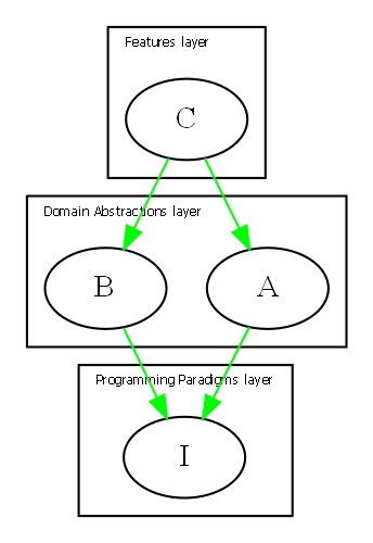
There is a Layers pattern that also controls dependencies, but since most systems have numerous run-time dependencies between elements represented as design-time dependencies, these layers are used for the run-time dependencies. It is usually explained that each layer is built on services provided by the layer below it.
One example is the UI/Business Logic/Data model. Another example is the OSI communications model, where the layers are Application, Presentation, Session, Transport, Network, Data link, and Physical. In ALA, each of these ends up being turned 90 degrees. Metaphorically they become chains. In ALA each component wouldn’t know about the components next to it. That applies symmetrically, to the left and to the right. Data goes in both directions. At run-time, everything must exist for the system to work. It doesn’t really make sense to use a asymmetrical layers metaphor.
The design pattern for layers does have one or two examples of layering used by knowledge dependencies. The term ‘layer’ is therefore an overloaded term in software engineering. When used for knowledge dependencies, the English term 'layer' is a better metaphor. If a lower layer of a wall were to be removed, the layers above would literally collapse, and that’s exactly what would happen in knowledge dependency layering. The layers above literally need the knowledge of abstractions in lower layers to make any sense.
ALA’s ripple effects are already under control because the only dependencies are on abstractions, which are inherently stable, and furthermore, those abstraction must be more abstract. However, to make these dependencies even less likely to cause an issue during maintenance, we try to make the abstraction layers discrete, and separated by approximately an order of magnitude. In other words each layer is approximately an order of magnitude more abstract than the one above it. More abstract means more ubiquitous, so the layers contain abstractions which have greater scope, and greater potential reuse as you go down the layers.
We won’t need many layers. If you think about abstraction layers in the real world, we can get from atoms to the human brain in four layers. Remember the creativity cycle early in this article. We only need to go around the cycle four times to make a brain: Atoms, Molecules such as proteins, Cells such as neurons, neural nets, and finally the brain itself.
7.11.2. The four layers
We start with four layers. They have increasing scope as you go down. This type of layering was described by Meiler Page-Jones. Meiler Page-Jones’ names for the four layers are: "Application domain", "Business domain", "Architecture domain", and "Foundation domain".
ALA uses slightly different names: Application layer, Domain Abstractions layer, Programming Paradigms layer, and Language layer.
Application layer
The top layer has knowledge specific to the application, and nothing but knowledge specific to the application, i.e. representing your requirements.
A simple Application might wire a grid directly to a table. When Business logic is needed, any number of decorators (that do validation, constraints, calculations, filtering, sorting, etc.) can be inserted in between the grid and the table by changing the wiring of the application.
Domain abstractions layer
Knowledge specific to the domain goes in this layer. A domain might correspond to a company or a department. As such, teams can collaborate on the set of abstractions to be provided there.
Applications have knowledge dependencies reaching into this layer.
Programming Paradigms layer
All knowledge specific to the types of computing problems you are solving, such as execution models, programming paradigm interfaces and any frameworks to support these, is in this layer.
The Programming Paradigms layer will abstract away how the processor is managed to execute different pieces of code at the right time. Execution models are covered in detail in chapter four.
This layer is also where we arrange for our domain abstractions to have common simple connections instead of having a specific language for each pair of modules that communicate. The Programming Paradigms layer abstracts away ubiquitous communications languages (which we have been referring to as programming paradigms in this article.)
Let’s use the clock as a real world example. (This is the same clock example we used in section 2.9 when introducing the role abstractions play in the creative process.) One of the the domain abstractions for clocks is a cog wheel. Cog wheels communicate with one another. But they don’t do it with communications languages specific to each pair, even though each pair must have the correct diameters and tooth sizes to mesh correctly. The cog abstraction just knows about the common paradigm of meshing teeth, a more abstract language in this lower layer. This language is analogous to a programming paradigm. With it, the clock abstraction (which is in the highest layer) can then instantiate two cogs and configure them to mesh. The concept of cog thus remains an abstraction and instances of it are composable. The clock, which already knows that two instances of cogs are needed, also knows where they will be fitted and what their diameters must be. The knowledge in the clock abstraction is cohesive.
Language layer
The language layer is included to show what is below the other three layers. It is not hardware as you would find in many other layering schemes, nor is it a database, because it is not run-time dependencies we are layering. The lowest layer has the remaining knowledge you need to understand your code, that of the languages, libraries and any very generic APIs you may use.
The hardware and database do have a place, but we will cover it later. Being a run-time dependency, it will be well off to one side and slightly higher up.
Domain Abstractions API
The boundary between the application layer and the domain abstractions layer is an API that supports the solution space of your requirements (within the constraints of your domain).
The scope of the Domain Abstractions layer defines the expressiveness available to the application. The greater the scope (or bigger the domain), the more applications are able to do. The cost is expressiveness. The applications will have to be longer to specify what is to be done. Conversely, a smaller domain allows less versatility in the applications, but there is greater expressiveness, which means you write less code.
Possible extra layers
The domain is an approximation of all the potential applications and all the modifications you are likely to make. If the domain is large because it is enterprise wide, you could have an additional layer for small domains. The enterprise domain would include enterprise wide abstractions such as a person identity, and the smaller domains would add additional, more specific abstractions, such as a customer (by composition).
If the applications are large and themselves need to be composed of features, an additional layer that supports plug-in style abstractions may work well. Plug-in abstractions may actually be instances of domain abstractions, such as a settings Menu, or a customer Table. A feature can then add settings to the menu, or columns to the table that remain unknown to any other features.
Programming Paradigms API
The boundary between all higher layers and the Programming Paradigms layer is another API. It separates the domain knowledge from the programming paradigm implementation knowledge. It almost always takes care of the ‘execution flow’, the way the computer CPU itself will be controlled to execute all the various parts of the code and when, often using a framework. On the other hand, the Programming Paradigms layer doesn’t necessarily have any code at all. Remember that the layers are ‘knowledge dependencies’, not run-time dependencies, so the paradigm could be a ‘computational model’ that just provides the knowledge of patterns of how to constracut the code in higher layers. The decisions about use of the patterns and about the way the code is executed have already been made and exist in the Programming Paradigms layer.
Rate of change of knowledge
The knowledge in each of the four layers has different change rates.
-
The Language layer contains knowledge that will likely change only a few times in your career.
-
The Programming Paradigms layer knowledge changes when you move to different computing problems types, or discover different approaches to solving a broad range of problems. For example, if you have not yet used an event driven execution model or state machines in your career, and you move into the embedded systems space, you will very likely need to have those skills.
-
The Domain Abstractions layer has knowledge that changes when you change the company you work for. It will change at the rate that the company’s domain is changing, or is becoming better understood. If your company uses lean principles, one of the things you want to do is capture knowledge for reuse. This is the whole point of the Domain Abstractions layer, it is a set of artefacts that capture the company’s reusable knowledge.
-
The Application layer has the fastest changing knowledge, the knowledge that changes at the rate that an application gets maintained.
7.12. Composition versus decomposition
Here we revisit the important idea introduced in chapter 3 to do with the pitfalls of thinking in terms of hierarchical decomposition.
In decomposition methods, we are taught to decomposes the system into smaller elements or components with relations between them. Then decompose those into still smaller ones. The process continues until the pieces are simple enough to understand and implement. Each decomposition artefact is completely contained inside its parent artefact, so it forms a hierarchical encapsulation structure.
|
Decomposition of the system into elements and their interactions. |
The decomposition approach is often the de facto or informal method used by developers because it is encouraged by many architecture styles and patterns, for example components or MVC. It is the method used in ADD (Attribute Driven Design). Indeed some definitions of software architecture sound like this meme:
-
From Wikipedia quoting from Clements, Paul; Felix Bachmann; Len Bass; David Garlan; James Ivers; Reed Little; Paulo Merson; Robert Nord; Judith Stafford (2010:
"Each structure comprises software elements, relations among them, and properties of both elements and relations."
-
IBM.com
"Architecture is the fundamental organization of a system embodied in its components, their relationships to each other, and to the environment, and the principles guiding its design and evolution. [IEEE 1471]
-
synopsys.com
"Architecture also focuses on how the elements and components within a system interact with one another."
-
From an article on coupling by Martin Fowler https://www.martinfowler.com/ieeeSoftware/coupling.pdf
"You can break a program into modules, but these modules will need to communicate in some way—otherwise, you’d just have multiple programs."
-
Loose coupling and high cohesion
The "loose coupling and high cohesion" meme suggests that loose coupling is the best we can do. We are told that modules or components must collaborate in some way. It seems reasonable and even self-evident. So why is it completely wrong? It’s because we are thinking in terms of decomposition. There is another way - composition.
To be fair, some of the examples above are vague enough to be interpreted in either way. But all are misleading in that they are suggestive of the idea of decomposition.
To fix the problem, we should re-word the meme:
|
Expression of the requirements by composition of abstractions. |
All four big words are changed and some are exact opposites. Indeed, the architecture that comes out of this method is "inside out" when compared to the decomposition method.
Let’s contrast two pseudo-structures: one that results from the decomposition approach and one that results from the composition approach.
7.12.1. Decomposition of the system into elements and their interactions
This diagram shows a decomposition structure. The outer box is the system. It shows decomposition into four elements, and then those in turn are decomposed into four elements each.
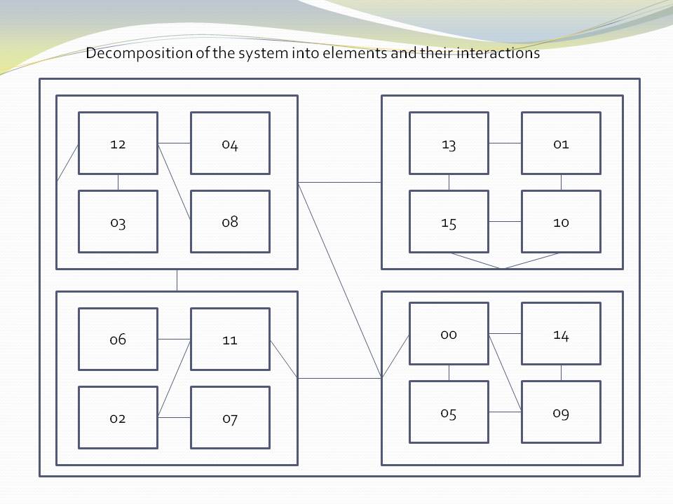
The outer elements correctly only refer to the outer interface of the components - their package or namespace interface, facade, or aggregate root - however you want to think of it. Encapsulation is used at every level of the structure to hide implementation details.
The elements are labelled with numbers to emphasise that they are not good abstractions. Of course, in practice these elements have a name.
The next diagram shows the same structure but with parts relevant to a user story marked in red. This is the "their interactions" part of the "The decomposition of your system into elements and their interactions".
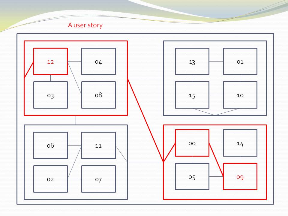
The diagram shows both decomposition relationships (boxes inside boxes) and interaction relationships (lines).
7.12.2. Expression of the requirements by composition of abstractions
This diagram shows a composition structure.
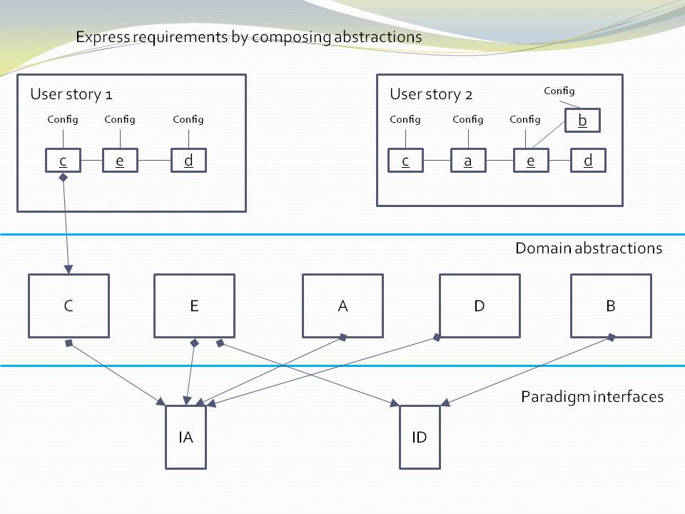
Only 'composition' relationships are present. We have shown some of them as lines even though you wouldn’t normally draw them. For example, the one from c to C. In practice we wouldn’t normally draw a diagram like this at all - the abstractions would be just referred to by name. But here we are trying to make a combined diagram of the meta-architecture and the specific architecture. The meta-architecture is the three layers, and the knowledge dependencies that go from the higher layers to the lower layers. The specific architecture consists of the diagrams inside the user stories in the top layer, the specific composition of instances.
Note that although we use lines in the diagrams in the top layer, those lines do not represent dependencies.
7.12.3. Comparison of the two approaches
| Decomposition | Composition |
|---|---|
|
|
Hierarchical (fractal) structure |
Layered structure |
Elements become less abstract as you zoom in. They are specific parts of specific parts. They have no use in another part of the decomposition. |
Parts become more abstract as you go down the layers. They are reusable in many parts of the application. |
Elements have no use in another part of the application. |
Elements are reusable in many parts of the application. |
Hides details through encapsulation, which works at compile-time. |
Hides details through abstraction, which works at design-time. |
Encapsulates abstractions |
Encapsulates instances of abstractions. |
Inner parts are increasingly private. They are encapsulated in increasingly smaller scopes. These private parts still need to be known about at design-time to understand the system (unless they happen to also be good abstractions). |
Lower layers are increasing public. Only the abstractions themselves are needed to understand the system. |
Dependencies go in the direction from the outermost element to the innermost. This is the direction of less abstract and therefore less stable. |
Dependencies go down the layers. This is the direction of more abstract, and therefore more stable. |
Dependencies also exist between parts at the same hierarchical level |
There are no dependencies between abstractions at the same layer. |
Encourages the same element to be used for both abstraction and instance - often called a module or component. |
Clearly has two distinct types of elements - abstractions and instances. |
Elements are loosely coupled. |
Abstractions are zero coupled. |
Discourages reuse. 16 elements all different from each other. |
Encourages reuse. Only 5 abstractions. 16 instances of those five abstractions. |
SMITA - Structure missing in the action. If you are interested in a particular user story, you will typically have to trace it through multiple elements, multiple interfaces, and their interactions across the structure. An example of this is shown by the diagram with the red lines. |
Eliminates this problem. The structure is explicit and in one place. |
Coupling increases during maintenance. This is because details are not hidden inside abstractions, only encapsulations. Any of them can be needed at any time by an outer part of the structure. So as maintenance proceeds, more of them will need to be brought into the interfaces, increasing the coupling as time goes on. |
Coupling remains at zero during maintenenace. Abstractions represent ideas, and ideas are relatively stable even during maintenance. All the dependencies are relatively unaffected. An operation called generalizing an abstraction is sometimes done. This increases the versatility, reuse and ubiquity of abstractions over time. |
Complexity increases as the system gets larger. |
The complexity stays constant as the system gets larger. Each abstraction is its own stand-alone program. If we choose an ideal granularity of say 200 lines of code, the complexity in any one part of the program is that of 200 lines of code. |
The maintenance cost (effort per user story or effort per change) increases over time. This is because complexity is increasing. Changes will tend to have ripple effects, but that isn’t the biggest problem. Even if a change ends up being in one place, reasoning about the system to determine where that change should be can require reasoning across the system. |
The maintenance cost reduces as the system grows. This is because as the domain abstractions mature, the user stories become less and less work to do - they simply compose, configure and wire together instances of existing domain abstractions. |
7.12.4. Transforming a decomposition structure into a composition structure
-
The structure turns inside out. Abstractions are found in the inner-most encapsulations. These are brought out to be made public, reusable, ubiquitous and stable at the domain abstractions layer.
-
The parts of the inner encapsulations that are specific to the application are factored out to become configuration information in the application layer, which it uses when instatiating abstractions.
-
Dependencies that existed between encapsulated elements for run-time communications are eliminated. They become simple wiring up of instances inside the application.
7.12.5. Smells of decomposition
-
Hierarchical diagrams
The tell-tale sign that this is happening is when we draw hierarchical diagrams. Boxes contained inside boxes. Even if we don’t draw them that way, the 'containment' or encapsulation is still implied. This is what package and component diagrams do. ALA has no use for package diagrams in the logical view. (However, they are still relevant in other views. There are several good reasons to have separately deployable binary code units such as exes or dlls.)
-
The dependency graph has many levels
If you have avoided circular dependencies, your application can be viewed as a (compile-time) dependency graph. Because it has run-time dependencies, it will have many 'levels'. These are not the hierarchical encapsulation levels, but just the strings of run-time dependencies within each level. In a composition system, the dependency graph will have a low number of layers.
-
Encapsulation without abstraction
Encapsulating details without an abstraction causes module or component boundaries to look relatively transparent at design-time. Their interfaces will tend to be specific to pairs of modules, and will tend to get increasingly wide as the software life cycle proceeds.
-
Modules have responsibility for who they communicate with
Either the sender knows who to send messages to, or, if using publish/subscribe, the receiver knows who to receive messages from. Understanding the system requires reading inside the parts to get the interconnection knowledge.
-
Compile-time indirection
If you find yourself doing many 'all files' searches to trace the flow of data or execution, this is a decomposition smell. The connections between the decomposed elements are mostly in the form of direct function calls or new keywords, and the name of another module. You have to find all these symbolic connections to trace through the system. In a composed structure, these connections are just adjacent elements in the text, or lines on a diagram. In both cases they are annonymous.
-
Run-time indirection
To avoid circular dependencies, many of the Compile-time indirections would have been changed to run-time indirections. This is often done using observer pattern of automatic dependency injection.
There is a meme that says something to the effect that such indirection is a two edged sword. On one hand it reduces coupling but on the it makes the structure even harder to see than it was when you has 'all files' searches. You may have to resot to a run-time debugger to see where the bugger goes next. At first this seems reasonable. It seems that you must always have this compromise between explicit structure and loose coupling. However it is just a result of decomposition., and unnecessary.
|
In ALA, there is no conflict between indirection and an explicit structure. |
In a composition structure, at the top layer, all the structure is explicit in the form of the wiring. This is where all the design-time knowledge about the interactions between instances belongs, and where you can trace messages through the system at design-time with neither 'all files' searches, nor a debugger. When a message is processed by an instance of an abstraction, you know what that abstraction is supposed to do. You can tell if an issue is in the application or if an abstraction is not doing what is expected of it.
When you drop down inside an abstraction, you are now in a different program, bordered by its inputs and outputs. You don’t need to know where the execution flow goes outside its I/O ports to understand how it works because an abstraction has no knowledge of anything outside. If the abstraction calculates the squareroot and doesn’t do it correctly, you only need to debug to its interfaces.
ALA overturns the conventional meme about decomposition into elements and their relations. It is unnecessary to write software that way. The only relationship that remains is the 'use of an abstraction'. This is, of course, a dependency but it is a good dependency. We will discuss from the point of view of good and bad dependencies in a later section. For now, dependencies are good if we want more of them. The more of them the better. For example if you have a library function or class, say squareroot, the more it is used the better, because the more useful the library function must have been. This type of dependency, the 'use of an abstraction', is the only one you need to build a system.
If the domain were for building model toys, the non-ALA method would start with the imagined toy and decompose it into parts specific to that one toy. The solution would be brittle and hard to change and no other toys would be possible without the same huge effort all over again. The ALA method is Lego. You invent a finite set of abstract building blocks and the mechanisms by which they connect. Then the initial toy can be easily changed, and other toys are possible with the same abstractions.
7.13. 4+1 views
7.13.4. Physical view
If the system is deployed on multiple machines (this is the subject of the physical view), the ALA abstractions, layers and diagrams all remain identical.
Ideally, the performance view also does not affect the ALA logical view. This is a many faceted problem that we will return to later.
ALA usually works very well with aspects of the development view as discussed elsewhere. For example, the fact that domain abstractions have zero coupling greatly helps the allocation of teams. The teams need only cooperate on a common understanding of the programming paradigms used.
7.14. No separation of UI
In ALA we don’t separate the UI unless there is a reason to do so. The amount of knowledge in the UI that comes from a particular application’s requirements is usually quite small and that knowledge is usually quite cohesive and coupled with the business logic of the feature it belongs with. For example, the layout of the UI is a small amount of information, and the bindings of the UI elements to data are a small amount of information. So all that cohesive knowledge is kept together, encapsulated inside a feature. Instead, the UI is composed from Domain UI abstractions. Being domain specific, these abstractions have a little more knowledge to them than generic widgets. For example, their domain knowledge may include style, functionality and suitability to their domain context. For example, a softkey or menu item will have an appearance, functionality and suitability to the way UIs are designed in the domain. Using one in a specific application only requires a label and a binding to an action. They will also provide consistency in the domain.
If there is an actual requirement to have different UIs, say a command based UI and a GUI based UI, then you just abstract the UI abstractions further until they can be used either way. The UI abstractions still remain an integral part of the application.
In the example project for this chapter, we will for the first time use multiple programming paradigms, a usual thing in real ALA projects.
7.15. Features
You may have noticed throughout this article the word 'features' being used quite often instead of 'Application'. When the application is large, we can think of it as a composition of feature abstractions. This is exactly what happens in natural language in the domain when describing requirements. 'Features' is just the word we give the natural abstractions in the requirements, without even realizing it. Just go with this in the software itself.
7.16. Inheritance
ALA doesn’t use inheritance because in the real world things are composed of other things. The only place inheritance occurs is in the tree of life. The down sides of inheritance are well documented. The indirect (virtual) method calls (polymorphism) when indirection is not required makes programs hard to follow. ALA of course uses polymorphism in the extreme (by its use of abstract interfaces as programming paradigms), but its always used when going up an abstraction level and never used to replace what should be explicit wiring.
I get the impression that most inheritance is lazy coding of what is really composition. For example, several abstractions, B, C, D are using another abstraction A. A client using say B makes a method call. The execution of the method is not overridden by B. Using inheritance, the call goes directly to A even though the call was made on object B. B doesn’t need any code that effectively says it has nothing to add. Using composition, B must handle the call first, and then pass the call through to A. This is extra code in B, C and D if none of them have any differences to add. In ALA we add this extra code in B, C and D, so no virtual methods (indirections) are involved and everything is explicit.
There is a potential use for inheritance in ALA. Abstractions can change over time and have versions. The open-closed principle asks us to allow for these changes without changing old code.
This is analogous to the case of inheritance that occurs in nature. We like to see modern species as differences with older common ancestors. We may want to represent code in the same way as old form + differences.
This is a highly dubious concept in my opinion because it is not sustainable. As the number of subclasses pile on top of each other over time, the old form + differences way of looking at it will seem less and less relevant. It’s a bit like the eventual mess that results from always using #ifdefs for modifications to C code. The #ifdefs are great at the time when the focus is on the differences, but those differences become unimportant later.
That said, we could invent a view to add to the 4+1 views that specifies the versions of every abstraction used in each application. Newer versions of every abstraction may become available, and this view can be changed when it is time to update a particular application to use the latest abstractions (when there is time to test it). The application itself doesn’t change, but the new view causes it to instantiate specified new versions. Since there may be a long period of deprecation of old abstractions, we may want to represent new versions as differences. Eventually when the old version is fully deprecated, it would be integrated into the next version up.
To achieve this the application code would not use new itself. Instead every abstraction would include a factory. The factory would read information from the new view and return the correct version. Note that even this scenario doesn’t require inheritance. The difference abstraction may just be composed of the older unchanged abstraction.
This is a topic for future research.
7.17. Horizontal domain partitions
Say you are implementing a particularly large domain abstraction such as a 'Table', or are implementing a complicated programming paradigm. We would like to break these up into smaller components. Do we introduce a fractal type of structure to deal with this? Should we have hierarchical layers within layers contained completely inside the Table abstraction?
The astute reader will have noticed the non-ALA thinking in the statement "break these up into smaller components". In ALA we don’t decompose a large abstraction into components, we compose it from abstractions, which if necessary we invent as we go. These new abstractions will have a scope or level of ubiquity, stability and reuse that corresponds to one of the existing layers. So there should be no hierarchical or fractal structures in ALA.
However, the domain that these new abstractions are in won’t be the same domain as the one that provides for the writing of Application requirements. For example, the implementation of the Table abstraction will need to be connected to another abstraction in the domain of databases. One of the abstractions in that domain will know about a particular database, say SQL Lite. A polymorphic interface should exist between the two. That interface, being more abstract than either the Table or the SQL Lite abstractions, will be in the next layer down, where both the Table and the MySQL abstractions can have a knowledge dependency on it. Of course the SQL abstraction will actually be further composed of an adapter and a real database.
Some application domain abstractions are complicated. Examples of these are abstractions requiring a connection to an actual database, actual hardware, the Internet, etc. Implementing these will typically wire out horizontally into other technical domains. You can visualise them going in multiple directions, which is exactly the idea of Alistair Cockburn’s hexagonal architecture.
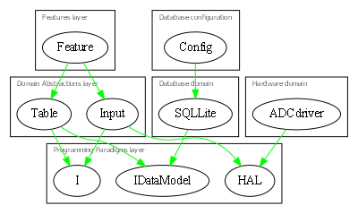
A communications domain using a OSI model may end up with a whole chain of communications domain abstractions going sideways:
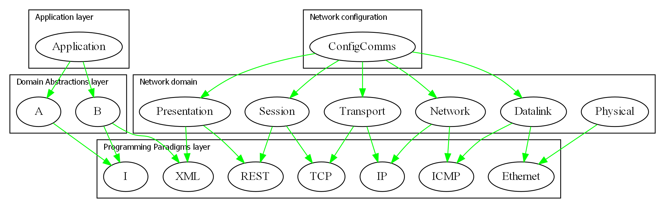
The technicalities may be incorrect but the diagram gives the idea of how the OSI 'layers', which are just run-time dependencies, would fit into the ALA layers.
7.18. No hierarchical design
ALA does not use any form of hierarchical structure. Instead it uses abstraction layers, together with "Horizontal domain partitions" discussed earlier.
7.19. Domain oriented
As has been found useful in other methodologies such as Domain Specific Languages, Domain Driven Design, Model Driven Software Development and Language Oriented Programming, ALA provides a way to be 'domain oriented'.
But unlike most of the other domain oriented methodologies, ALA provides a way to be domain oriented with ordinary code, and with the same development environment. It is just a way to organise ordinary code to be domain oriented.
7.23. Symbolic indirection
| Avoid use of symbolic indirection without abstraction |
When we start assembling requirements from abstractions, a topic that we will cover in coming sections, we will be using symbolic indirection, such as function calls or the new keyword with a class name. Unless a symbolic indirection is to an abstraction, they are for the compiler to follow at compile-time, not for the code reader to follow at design-time. Understanding the code relies on allowing the reader to read a small cohesive block of code. The reader should never have to follow the indirection somewhere else. If you don’t achieve this, and abstraction is the only way you can, then any decoupled architecture will be more difficult to read.
Abstraction allows indirection while allowing the reader to continue reading on to the next line. The importance of this property cannot be overstated. As soon as we start thinking in mere programming language terms of modules, components, interfaces, classes, or functions, the abstraction will start to be lost. These other artefacts may have benefits at compile-time (the compiler can understand them), but that is not useful at design-time unless they are also good abstractions.
It would be nice if your compiler could tell you that you have a missing abstraction, just as it does for a missing semicolon, but alas, they are not capable of understanding abstractions yet. So it is still entirely up to you.
Abstraction is almost a black and white type of property. It’s either there or it isn’t. If the reader of your code does not have to follow the indirection, you have it.
Footnote: When the reader of your code meets your abstraction for the first time (usually a domain abstraction in a domain they have recently come into), ideally their IDE will give them the meaning in a little pop-up paragraph as their mouse hovers over any of its uses. Depending on the quality of the abstraction, after a single exposure, their brain will have the insight, like a light coming on, illuminating a meaning. The brain will form a new neuron to represent the concept. Since the reader will hopefully remain in the domain for some time, this overhead to readability shouldn’t be large.
7.24. Everything through interfaces
A class, in contrast to an abstraction, has an interface comprising all the public members. In ALA we only want this interface to be used by the application when it instantiates and configures an instance of an abstraction. All other inputs and outputs that are used at run-time are done through interfaces (abstract interfaces).
7.25. What do you know about?
Whenever I have only two minutes to give advice on software architecture, I use this quick tip. The tip is ALA reduced to its most basic driving principle.
Ask your modules, classes and functions:
|
What do you know about? |
The answer should always be "I just know about…".
The anthropomorphization helps the brain to see them as abstractions. The word 'knows' is carefully chosen to imply a 'design-time' perspective.
-
It’s a restatement of the SRP (Single Responsibility Principle). Every element should know about one thing, one coherent thing. Furthermore, no other elements should know about this one thing.
-
An element may know about a single hardware device.
-
An element may know about a user story.
-
An element may know about a protocol.
-
An element may know an algorithm.
-
An element may know how to do an operation on some data, or the meaning of some data, but not both.
-
An element may know a composition of other elements.
-
An element may know where dataflows between other elements.
-
No element should know the source or destination of its inputs and outputs.
7.26. Example project - a real device
Unlike our previous example projects, this project is a real device and had previously been implemented without any knowledge of ALA. So this example serves to make comparisons between ALA and conventional software development. The original software was around 200 KLOC and took 3 people 4 years to write.
The actual device is used by farmers all over the world. It can weigh livestock and keeps a database about them for use in the field. It connects to many other devices and has a large number of features:

The architecture in the original software, was somewhat typically organised into modules and patterns by its developers. Also somewhat typically, it had ended up with a high cost of modifiability - a big ball of mud. After the first release, the first incremental requirement was a 'Treatments' feature, which involved several new tables, new columns in existing tables, new data pages, new settings pages and some new business logic. This feature took a further 3 months to complete (actually 6 calendar months), which seemed out of proportion for the size of the feature. Somehow the Product Owner and managers seemed to have a sort of intuition that if similar things had been done before, such as menus or database tables, those things were already done, and the only new work was in the specific details of the new requirements. Those requirements could be communicated in a relatively short time, say of the order of one hour or one day if you include follow up discussions of abnormal scenarios. So 6 months did not go down well. ALA, of course, works in exactly this intuitive way that managers hope for. All the things already done are sitting there in the domain abstractions, waiting to be reused, configured and composed into new requirements.
7.26.1. Iteration zero
During the development, there had a been a high number of changes required to the UI. It occurred to me at the time that the underlying elements of the UI were not changing. It was mainly the details of layout and navigation around the device’s many pages that were changing. The same could be said about the data and business logic. Only details were changing.
I took to representing the new designs using box and line drawings representing both the UI layouts and the navigation flows. I realized these diagrams were potentially executable, and wondered how far I could go representing the data and business logic in the same way. I decided to try to represent all of the functionality of the indicator in just one diagram.
It took two weeks to complete the diagram. I used Xmind because it laid itself out. I found that any drawing package that needed you to stop and do housekeeping such as rearranging the layout got in the way so much that you would lose your flow. Xmind allowed me to just enter in the nodes and it would automatically wire them in as either peers or chains and lay them out. The one disadvantage was that Xmind only does trees, so any cross tree relations had to be done manually, but this was also very quick in Xmind once you were used to it. I just let the cross wiring form arcs across parts of the tree.
Progress was extremely rapid once you had the abstractions and paradigms you needed. And many of them were obvious: softkeys, pages, grids, menus, actions, navigate-action, tables. etc. The programming paradigms would pop into play as needed. After the obvious UI-layout and navigation-flow ones came dataflow and dataflow of table types, events, and schema. The user of this device could set up custom fields, so the schema itself partially came from another table. At times I would get stuck not knowing how to proceed. The longest of these blocks was half a day. But every time the required abstractions or programming paradigms would firm up, and in the end anything seemed possible.
The diagram itself took shape on the right hand side of the Xmind tree. On the left side I had the invented domain abstractions and paradigm interfaces, with notes to explain them. The right side was mostly just a set of relatively independent features, but there was the odd coupling between them such as UI-navigation lines that were also present in the requirements.
The diagram contained around 2000 nodes (instances of the abstractions), which is about 1% of the size of the total original code. There were about 50 abstractions, and several paradigm interfaces.
Part of the diagram is shown below (laid out more nicely in Visio)
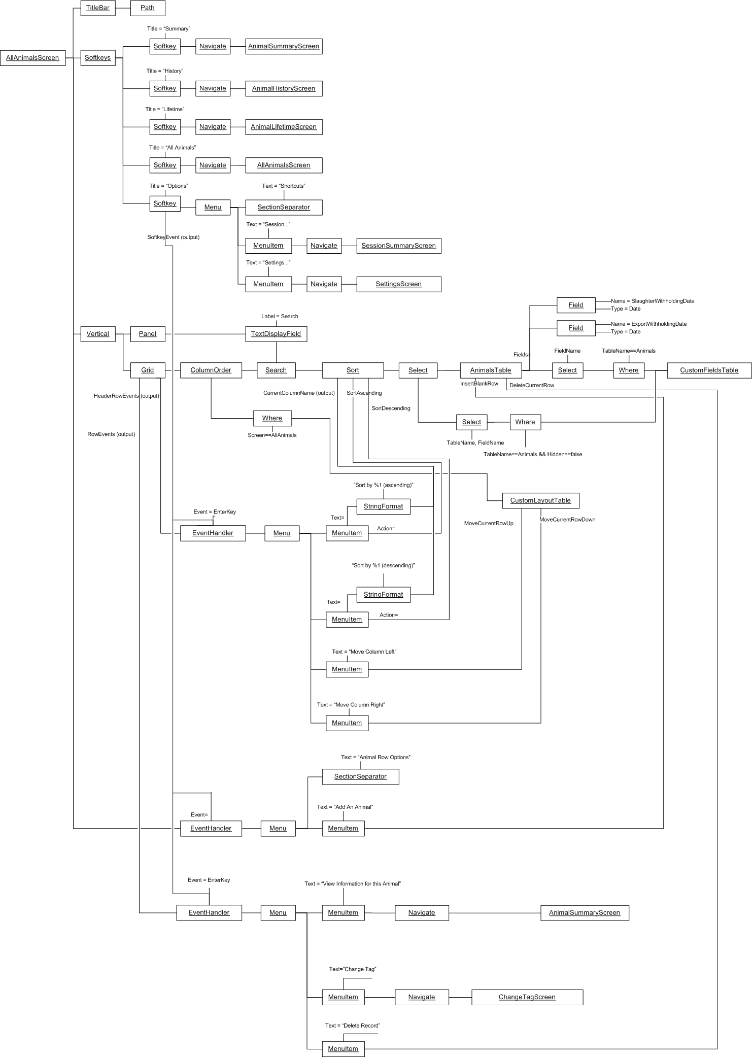
As I did the diagram, I deliberately left out anything to do with the aforementioned Treatments feature, so that I could see how easy it might have been to implement once the domain abstractions for the rest of the requirements had matured. So after the diagram was completed, I added the Treatments feature. This involved adding tables, columns to existing tables, a settings screen, a data screen, and some behaviours. No further abstractions needed to be invented. The incremental time for the diagram additions was of the order of one hour. Obviously testing would be needed on top of that, and the 'Table' abstraction would need additional work so it could migrate itself, a function it had not needed up until this point. Although somewhat theoretical, the evidence was that we could get at least an order of magnitude improvement in incremental maintenance effort.
At first the diagram seemed too good to be true. It had an elegance all of its own. It apparently captured all of the requirements, without any implementation at all, and yet seemed potentially executable. And if it worked, application modifications of all the kinds we had been doing were going to be almost trivial.
The burning question on my mind was, is it simply a matter now of writing a class for each of these abstractions and the whole job is done?
7.26.2. Translating the diagram to code
We hired a C++ student and proceeded with a 3-month experiment to answer this question.
It was a simple matter to translate the diagram into C++ code that instantiated the abstractions (classes), wired them together using dependency injection setters, configured the instances using some more setters, and used the fluent interface pattern to make all this straightforward and elegant. Part of the code for the diagram sample above is shown below to give you a feel for what it looked like.
m_animalListScreen
->wiredTo((new Softkeys())
->wiredTo((new Softkey())
->setTitle("History")
->wiredTo(new Navigate(m_animalHistoryScreen))
)
->wiredTo((skeyOptions = new Softkey())
->setTitle("Options")
->wiredTo(new Menu()
->wiredTo(new Navigate("Session...", m_sessionSummaryScreen))
->wiredTo(new Navigate("Settings...", m_settingScreen1))
)
)
)
->wiredTo((searchField = new TextDisplayField())
->setLabel("Search")
->setField(VIDField = new Field(COLUMN_VID))
)
->wiredTo(new Grid()
->wiredTo(columnOrder = new ColumnOrder())
->setRowMenus((new EventHandler())
->setEvent(EVT_KEY_ENTER)
->wiredTo(new Menu()
->wiredTo(new Navigate("View information for this animal", m_animalSummaryScreen))
->wiredTo((new Action("Delete Record", AnimalsTable::DeleteRow))->wiredTo(AnimalsTable))
)
)
);
7.26.3. Writing the classes
We knew we wouldn’t have time to write all 50 classes, so we chose to implement the single feature shown below as a screen shot.
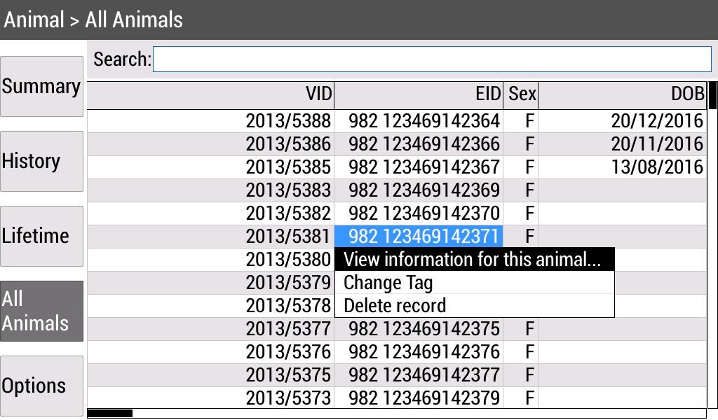
The student’s job was to write 12 abstractions out of the 50. These 12 were the ones used by that feature. The initial brief was to make the new code work alongside the old code (as would be needed for an incremental legacy rewrite), but the old code was consuming too much time to integrate with, so this part was abandoned.
The learning curve for the student was done as daily code inspections, explaining to him where it violated the ALA constraints, and asking him to rework that code for the next day. It was his job to invent the methods he needed in the paradigm interfaces to make the system work, but at the same time keep them abstract by not writing methods or protocols for particular class pairs to communicate. It took about one month for him to fully 'get' ALA and no longer need the inspections.
The student completed the 12 classes and got the feature working in the device. The feature included showing data from one database table in a grid, sorting, searching, softkeys, and a menu.
Interestingly, as the student completed certain abstractions that allowed parts of other features to be done, he would quickly go and write the wiring code and have the other features working as well. For example, after the softkeys, actions, navigate, and page abstractions were done, he went through and added all the softkey navigations in the entire product as this only took minutes to do.
We wanted more funding to retain the student until we had enough to do the treatments feature, and indeed all 50 abstractions with the hope of making this implementation the production code and improving our ongoing maintenance effort. But that was not to be, despite the promising result.
We have about a quarter of a data point. Some of the abstractions done were among the most difficult, for example the Table abstraction, which had to use SQL and a real database to actually work. So it is not unreasonable to use extrapolation to estimate that the total time to do all 50 abstractions would be about one person-year. That compares with the original 12 person-years.
It seems that classes that are abstractions are faster to write. This seems intuitive because you don’t have any coupling to worry about. More importantly, the two phase design-then-code methodology of ALA allows the developer not to have to deal with large scale structure at the same time as writing code. This frees the developer to go ahead and write the code for the local problem.
I believe it is beneficial for each developer to be trained to be both an architect and a developer, but just don’t ask them to do both at the same time.
This practical result combined with the theory outlined earlier in this article suggests there ought to be a large improvement in incremental maintenance effort over a big-ball-of-mud architecture.
8. Chapter eight - Surrounding Topics
8.1. Recursive abstractions
ALA enforces a strictly layered (non-circular) knowledge dependency structure. It encourages a small number of abstraction layers at discrete well separated levels of ubiquity as a framework for the knowledge dependencies. This would appear to exclude the possibility of the powerful abstraction composition technique of recursion, where the meaning of an abstraction is defined in terms of itself. (Or an abstraction implementation may need knowledge of another abstraction, which in its turn has an implementation that needs knowledge of the first abstraction. This appears to require circular knowledge dependencies.
Circular knowledge dependencies happen all the time in functional programming where recursion replaces iteration. This is generally when a function needs to call itself or a class needs to use 'new' on itself. For example, a recursive descent compiler will have a function, 'statement', which will implement specific statements such as 'compound statement', 'if statement' and so on, and in those there will be a recursive call to the function, 'statement'. The following Syntax diagram represents part of the implementation of function 'statement'.
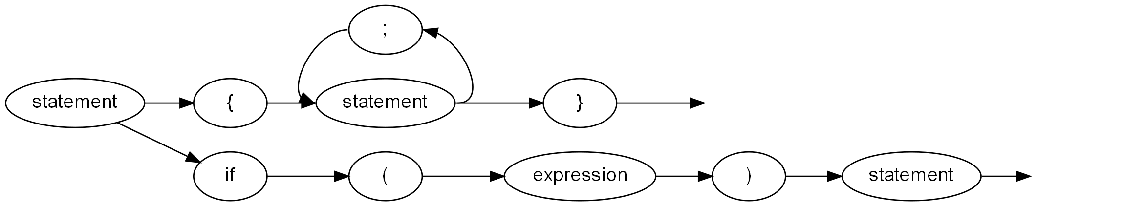
In ALA, we want to preserve the idea of clear layers defining what knowledge is needed to understand what. Resolving this dilemma could get a bit philosophical. Since abstractions are the first class artefacts of the human brain, it may be best to think about how the brain does it. The brain must actually have two abstractions with the same name but at different levels. The first is analogous to a 'forward declaration' in a language to allow a compiler to know about something that will be referred to in a more abstract way before it finds out about it in a more specific way.
By this analogy, ALA sometimes requires the concept of a forward-declared-abstraction, something that is clearly more abstract than the concrete implementations. Therefore, we can put this forward declaration in the next layer down, just as we would a paradigm interface. In the recursive descent compiler example, we would first have the abstract concept of a statement, meaning a unit of executable code as an interface in a lower layer. Then the specific abstractions, compound statement, if statement and so on are in a higher layer. They both provide and accept the interface.
Another language example is that an expression is composed of terms, a term is composed of factors, and a factor can be composed of expressions (enclosed in round brackets). If we model these compositions as direct knowledge dependencies, we would have too many layers - and they would not be becoming more abstract as we go down. The existence of the recursion at the end reinforces that. It seems that all three, expressions, terms and factors, should have abstract interface versions at a lower level.
Not all cases of recursion would require these interfaces. If, for example, in your old way of doing things there is a long chain of function calls, with the last one calling the first one, all of them are probably run-time dependencies, not knowledge dependencies at all. So in ALA, they should all be changed to be wirable, and wired together by an abstraction in a higher layer. The paradigm interface that is used to allow them to be wired may be,for example, dataflow. So recursion does not necessarily require different interfaces for each different abstraction involved in the circular dependency.
8.2. Abstraction of Port I/O properties
This is an advanced topic that allows abstractions to be written without knowing details of the implementation of the communications. The idea is for the language to support logical or abstracted I/O ports that work for any type of technical communication properties such as described in the sections below. If we allow these properties to be binded late, say at compile-time, they can be changed independently of the domain abstractions. This allows tuning of performance or physical deployment of the abstractions to different processes or hardware.
I have been looking into how this could be accomplished using a conventional language, but it seems quite hard.
8.2.1. Push or Pull
Say an abstraction has a single logical input that can be wired to and a single logical output that can be wired from. Both the input and the output could be used in either a push or a pull manner.
For the input, push means we will be called with the data. Pull means we will call out to get the data.
For the output, push means we will call out with the data, and pull means that something will call us to get the data.
There are four combinations possible:
-
push push : push through
-
pull pull : pull through
-
push pull : internally buffer the input or output
-
pull push : active object
Let’s imagine we have a function that processes the data inside the abstraction.
The four combinations would require the function to run as a result of a function call from the input, or a function call from the output. The function result may be put into an internal buffered or be pushed out. The function may need to receive its input from an input buffer or by pulling. The function may need to run via a 3rd input that is polled or called by a timer.
We could conceivably write an abstract I/O class with an output interface and an input interface and a configuration interface that allows it to be configured late on how to do the I/O. This abstract I/O object would call the function to do the work at the right time according to its configuration.
8.3. Working with legacy code
In old (non-ALA) legacy code, abstractions, if they ever existed, have usually been destroyed by coupling. If there is no model left by the original designer, or it is out of date, I first create one. I usually have to 'reverse engineer' the model by doing many 'all files searches' and trying to build a mental picture of how everything fits together. It can quickly become mentally taxing if the user story is non-trivial. So I build a UML class diagram from the searches (their one useful application) as the background (using light lines), and a tree of method calls for the specific user story on top of it (using heavier lines). These diagrams can end up looking pretty horrific, because the knowledge of the user-story has become so scattered, especially when inheritance is involved. The tree of method calls will come into the base class but leave from a subclass method.
This process can take several hours to a day for a single user story. Once the code for the single user story is understood, some acceptance tests are put in place for it, by putting in insertion points as close as practical to the inputs and outputs for the user story.
The next step is to factor out the method call tree for the user story into a new abstraction. This typically contains a sequence of new abstract activities or data transformations. These new abstractions are pitched at the domain level. Sometimes, if in C#, I will use Reactive Extensions. The user story may become a single RX sequence. The abstractions are then implemented, with tests, by copying and pasting useful code snippets from the original classes into the new abstractions. The old classes are marked for deprecation.
Conversion of user stories takes place iteratively.
8.5. Debugging ALA programs
Because in ALA you can get multiple instances of the same class used in multiple places, and multiple implementations of the same interface used in different places, debugging is easier if the instances are able to identify themselves. For this reason I tend to have a local property in every class called Name. The property is immutable and set by the constructor.
8.6. ALA language features
One of my first hobby programming projects was a compiler for a C-like high level language for embedded systems. At the time I had lots of energy to write the compiler and optimize the object code (written in itself, the performance of both compiling and of object code execution beat the first C compilers to later appear by around a factor of ten) but I lacked a lifetime of experience to design a language. Forty years later, I feel as if it’s partially the other way around, at least for language feature that would support good architecture. The language I should have implemented way back then should have been an ALA language - one that supported ALA architecture by having the needed constraints.
It would have had Abstractions and Instances as first class elements. The name Abstraction is to reinforce the obvious use of the only type of element that the brain uses at design-time for any kind of separation of concerns.
It would support a single type of relationship - a knowledge dependency. You would have to define your four layers, and keep them in separate folders so you would be forced to decide at what abstraction level any given piece of design-time knowledge would go. Of course, it would only allow knowledge dependency relationships from one layer to a lower layer. If you wanted to add an extra layer to the chain of dependencies, that would be a bad design decision. For example, if your application is getting too large, you could create a layer between it and the domain abstractions layer called 'plug-ins'.
Instances would work like components in that they would have ports for I/O. Like interfaces, ports are defined in a lower layer. The only way of instantiating abstractions and connecting them together is inside an abstraction in a higher layer.
Abstractions would support multiple ports of the same interface. Current languages have the difficulty that you can only implement one interface of a given type, which we had to workaround by having connector objects.
Ports would support late configuration of all communication properties such as push, pull, asynchronous, synchronous (explained above) without changing the Abstraction.
Such a language would overcome many of the problems of current languages that encourage non-ALA compliant practices. But the invention of good abstractions in the first sprint of any green-field project would still be a skilled phase requiring an innate ability to abstract.